
.png
)


About
Magnet falling through a ring
|
When a magnet falls through a ring, current is induced in the ring. This phenomenon is called electromagnetic induction.
According to Faraday’s law, the induced emf is proportional to the negative of the rate of change of magnetic flux Φ. The direction of the induced current is determined by Lenz’s law, the induced current produces magnetic field which tends to oppose the change in magnetic flux that induces such currents.
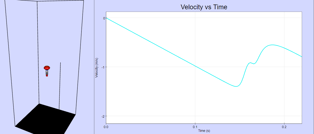
The voltage induced when a magnet is falling through a ring is simulated in this experiment, where we model the magnet as a magnetic 'dipole'. The current is visualized by very big 'electrons' that move according to the strength of the current. |
Please, complete this set of Minds-On questions:
- Explain the shape (positive and negative peaks) of the recorded signal.
- Why the peaks are not symmetric?
- At which moment was the magnetic flux changing most quickly?
- What was the total change of magnetic flux during the first half of the magnet’s fall - while it was moving in to the coil?
- What was the total change of magnetic flux during the second half of the magnet’s fall - while it was moving out of the coil?
- How could you change the simulation to increase the magnitude of the signal?
Translations
| Code | Language | Translator | Run | |
|---|---|---|---|---|
 |
||||
Credits


Maria Jose Cano; Fremont Teng; Ernesto Martin; Francisco Esquembre - Universidad Murcia; Loo Kang Wee
This document provides a review of the "Magnet Falling Through A Ring JavaScript Simulation Applet HTML5" resource available on the Open Educational Resources / Open Source Physics @ Singapore website. This resource is an interactive simulation designed to illustrate the principles of electromagnetic induction, Faraday's law, and Lenz's law. It models the voltage induced in a ring as a magnetic dipole falls through it and visualizes the induced current. The resource also includes "Minds-On" questions to guide student learning and offers various interactive controls for exploration.
Main Themes and Important Ideas
- Electromagnetic Induction: The core concept demonstrated by the simulation is electromagnetic induction. The introduction explicitly states: "When a magnet falls through a ring, current is induced in the ring. This phenomenon is called electromagnetic induction." This highlights that a changing magnetic flux through a conductive loop (the ring) will generate an electromotive force (EMF) and thus an induced current.
- Faraday's Law: The resource directly mentions Faraday's law, stating: "According to Faraday’s law, the induced emf is proportional to the negative of the rate of change of magnetic flux Φ." This fundamental law of electromagnetism governs the magnitude of the induced EMF. The simulation implicitly demonstrates this by showing a voltage signal that changes as the rate of magnetic flux through the ring changes.
- Lenz's Law: The resource also explains Lenz's law: "The direction of the induced current is determined by Lenz’s law, the induced current produces magnetic field which tends to oppose the change in magnetic flux that induces such currents." This law dictates the direction of the induced current, ensuring that the induced magnetic field counteracts the change in the original magnetic flux. The simulation visualizes this indirectly through the movement of 'electrons' representing the current, though the opposition of the magnetic field is more of a conceptual understanding students should derive.
- Simulation of a Magnetic Dipole: The "About" section notes the model used: "The voltage induced when a magnet is falling through a ring is simulated in this experiment, where we model the magnet as a magnetic 'dipole'." This indicates that the complexity of a real magnet is simplified to its fundamental magnetic field characteristic for computational purposes.
- Visualization of Induced Current: The simulation provides a visual representation of the induced current: "The current is visualized by very big 'electrons' that move according to the strength of the current." This helps students connect the abstract concept of induced current to a dynamic visual element.
- Interactive Learning: The resource is designed for interactive learning, offering several controls and "Minds-On" questions. The "Instructions" section details interactive elements such as:
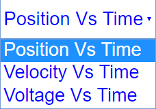
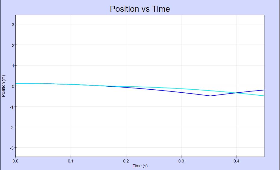
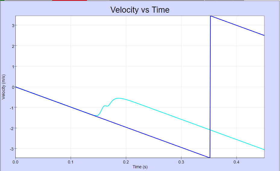
- Graph Combo Box: Allows users to view graphs of Position vs Time, Velocity vs Time, and Voltage vs Time.
- Cool Ring Check Box: Enables exploration of the effect of a cooled ring (presumably on resistance and thus current).
- North/South is Up Button: Allows flipping the magnet's orientation.
- Ring Size Field Box: Enables changing the dimensions of the ring.
- Free Falling Ball Check Box: Provides a reference for free fall motion.
- Play/Pause, Step and Reset Buttons: Standard simulation controls.
- Minds-On Questions: The inclusion of specific questions ("Explain the shape (positive and negative peaks) of the recorded signal," "Why the peaks are not symmetric?," etc.) encourages students to actively engage with the simulation and think critically about the observed phenomena in relation to the underlying physics principles. These questions prompt deeper understanding of the relationship between the magnet's motion, the changing magnetic flux, and the induced voltage.
- Open Educational Resource: The resource is explicitly identified as an Open Educational Resource, emphasizing its accessibility and potential for adaptation and reuse. The Creative Commons license information at the bottom confirms the terms of use.
Most Important Ideas and Facts
- Faraday's Law quantifies induced EMF based on the rate of change of magnetic flux.
- Lenz's Law dictates that the induced current creates a magnetic field opposing the change in magnetic flux.
- The simulation models a falling magnet as a magnetic dipole.
- Induced current is visualized through moving 'electrons'.
- The applet offers interactive controls to manipulate parameters like ring size and magnet orientation.
- "Minds-On" questions are integrated to promote active learning and critical thinking.
- The resource is part of a larger collection of Open Educational Resources in physics.
Implications and Potential Uses
This simulation applet is a valuable tool for teaching and learning about electromagnetic induction. Its interactive nature allows students to visualize abstract concepts and explore the relationships between different variables. The "Minds-On" questions can be used for formative assessment and to guide student inquiry. Teachers can embed this model into their webpages using the provided iframe code, making it easily accessible to students. The variety of controls allows for different experimental setups and investigations.
Further Considerations
- The level of detail in the theoretical explanation is concise. Teachers might need to supplement this with more in-depth discussions of Faraday's and Lenz's laws.
- The "Sample Learning Goals," "Research," and "Video" sections are marked as "[text]", suggesting that these areas might be incomplete or intended for further development.
- The extensive list of other available simulations highlights the breadth of resources offered by Open Educational Resources / Open Source Physics @ Singapore, covering a wide range of physics and mathematics topics.
This briefing document summarizes the key aspects of the "Magnet Falling Through A Ring JavaScript Simulation Applet HTML5" resource, highlighting its pedagogical value in illustrating fundamental principles of electromagnetism through interactive simulation
Magnet Falling Through a Ring: Study Guide
Core Concepts
- Electromagnetic Induction: The phenomenon where a changing magnetic flux through a loop of wire induces an electromotive force (EMF), which can drive an electric current.
- Faraday's Law: States that the induced EMF in any closed circuit is equal to the negative of the time rate of change of the magnetic flux through the circuit. Mathematically, EMF = -dΦ/dt, where Φ is the magnetic flux and t is time.
- Magnetic Flux (Φ): A measure of the total magnetic field that passes through a given area. It is defined as Φ = ∫ B ⋅ dA, where B is the magnetic field vector and dA is the area vector. For a uniform field perpendicular to a flat area, Φ = BA, where A is the area.
- Lenz's Law: States that the direction of the induced current in a closed circuit is such that the magnetic field created by the induced current opposes the change in magnetic flux that produces it.
- Magnetic Dipole: A model of a magnet where it is considered to have two poles, a north and a south, separated by a distance. The magnetic field lines emerge from the north pole and enter the south pole.
- Induced EMF: The electromotive force generated due to a changing magnetic flux.
- Induced Current: The electric current that flows in a closed circuit as a result of an induced EMF.
Key Principles from the Source
- When a magnet falls through a conductive ring, the changing magnetic flux through the ring induces an EMF.
- This induced EMF causes a current to flow in the ring (electromagnetic induction).
- The direction of this induced current creates a magnetic field that opposes the change in the original magnetic flux (Lenz's Law).
- The voltage induced in the ring is related to the rate at which the magnetic flux is changing (Faraday's Law).
- The simulation models the magnet as a magnetic dipole.
Simulation Controls and Observations
- Graph Combo Box: Allows you to view graphs of Position vs Time, Velocity vs Time, and Voltage vs Time. The Voltage vs Time graph displays the induced EMF as the magnet falls.
- Cool Ring Check Box: Likely affects the resistance of the ring. Cooling typically reduces resistance, which would lead to a larger induced current for the same induced EMF.
- North/South is Up Button: Flips the orientation of the magnet, which will reverse the direction of the magnetic flux change and hence the direction of the induced current and voltage.
- Ring Size Field Box: Changing the size of the ring will affect the amount of magnetic flux passing through it and how it changes as the magnet falls.
- Free Falling Ball Check Box: Allows comparison with a non-magnetic object undergoing free fall.
- Play/Pause, Step, and Reset Buttons: Control the simulation's execution.
Quiz
- Explain how Faraday's law and Lenz's law are both relevant when a magnet falls through a conductive ring. How do these laws determine the induced current in the ring?
- Describe the shape of the Voltage vs Time graph as a magnet falls through a ring. What causes the positive and negative peaks observed in the signal?
- According to Lenz's law, what is the direction of the magnetic field produced by the induced current in the ring as the north pole of the magnet approaches the ring from above? What happens as the north pole moves away from the ring?
- Why are the positive and negative peaks in the Voltage vs Time graph typically not symmetric in terms of magnitude and duration? What physical factors might contribute to this asymmetry?
- At what point during the magnet's fall through the ring is the magnitude of the induced voltage the greatest? Explain why this occurs at that specific moment.
- What is the total change in magnetic flux through the ring as the magnet falls completely through it (from a point well above to a point well below)? Justify your answer based on the initial and final positions of the magnetic dipole relative to the ring.
- How would decreasing the speed at which the magnet falls through the ring affect the magnitude and duration of the induced voltage pulse? Explain your reasoning based on Faraday's law.
- In the simulation, what are the 'big electrons' visualizing? How does their movement relate to the induced current in the ring?
- If the ring were made of a material with higher electrical resistance, how would this affect the induced current and the magnitude of the 'big electrons' movement for the same induced EMF? Explain.
- How would flipping the magnet (so the south pole falls through first instead of the north pole) affect the Voltage vs Time graph? Describe the changes you would expect to see.
Quiz Answer Key
- Faraday's law states that a changing magnetic flux induces an EMF, which drives the current. Lenz's law dictates the direction of this current: the induced current creates a magnetic field that opposes the change in magnetic flux.
- The Voltage vs Time graph shows a positive peak as the magnet approaches and enters the ring, indicating an increasing rate of change of magnetic flux in one direction. A negative peak occurs as the magnet leaves the ring, indicating a rate of change of flux in the opposite direction.
- As the north pole approaches, the flux through the ring increases downwards, so the induced current creates an upward magnetic field to oppose this increase (Lenz's law). As the north pole moves away, the flux decreases downwards, so the induced current creates a downward magnetic field to oppose this decrease.
- The asymmetry in the peaks can arise because the rate of change of magnetic flux is different as the magnet enters and leaves the ring. Factors like the changing distance and velocity of the magnet relative to the ring contribute to this.
- The magnitude of the induced voltage is greatest when the magnetic flux through the ring is changing most rapidly. This typically occurs when the magnet is passing through the plane of the ring, where the number of magnetic field lines passing through the ring is changing at the highest rate.
- The total change in magnetic flux as the magnet falls completely through the ring is zero. Initially, there is some flux through the ring in one direction, and after the magnet has passed, there is an equal amount of flux in the opposite direction (or vice versa, depending on the initial orientation). The net change from a point far above to far below is zero.
- Decreasing the speed of the falling magnet would decrease the rate of change of magnetic flux through the ring (dΦ/dt). According to Faraday's law (EMF = -dΦ/dt), this would result in a smaller magnitude of the induced voltage. The duration of the voltage pulse would also be longer as the magnet takes more time to pass through the region where the flux is changing significantly.
- The 'big electrons' in the simulation visualize the induced current in the ring. Their movement indicates the direction and strength of this current; a faster and more directed movement signifies a larger induced current.
- If the ring had higher resistance, for the same induced EMF, the induced current (I = EMF/R) would be smaller. Consequently, the movement of the 'big electrons' would be slower and less pronounced, indicating a weaker current.
- Flipping the magnet would reverse the direction of the magnetic flux change at each stage of the fall. This would result in a Voltage vs Time graph with the opposite polarity: the initial peak would be negative, and the second peak would be positive. The magnitudes and durations of the peaks would otherwise be similar, assuming the speed of fall remains the same.
Essay Format Questions
- Discuss in detail the interplay between Faraday's law and Lenz's law in the context of a magnet falling through a conductive ring. Explain how these fundamental laws govern the generation and direction of the induced current and voltage, and how this relates to the conservation of energy.
- Analyze the factors that influence the magnitude and shape of the induced voltage signal when a magnet falls through a ring. Consider the properties of the magnet (strength, dipole moment), the ring (size, material, temperature), and the motion of the magnet. How can the simulation be used to investigate these relationships?
- Explain the concept of magnetic flux and its rate of change. How does the changing magnetic flux through the ring as the magnet falls relate to the induced EMF, as described by Faraday's law? Discuss the significance of the negative sign in Faraday's law and its connection to Lenz's law.
- Describe how the simulation of a magnet falling through a ring provides a visual representation of abstract electromagnetic principles. Discuss the role of the 'big electrons' and the Voltage vs Time graph in helping to understand the phenomenon of electromagnetic induction. What are the limitations of this model?
- Consider real-world applications of the principles demonstrated by the falling magnet and ring simulation. Discuss examples where electromagnetic induction is utilized, such as in generators, transformers, and eddy current braking systems. How do the fundamental concepts illustrated in the simulation apply to these technologies?
Glossary of Key Terms
- Electromagnetic Induction: The production of an electromotive force (and thus an electric current) across an electrical conductor in a changing magnetic field.
- EMF (Electromotive Force): The energy provided by a source per unit of electric charge that is converted into electrical energy. Measured in volts.
- Faraday's Law of Induction: A fundamental law of electromagnetism stating that the induced EMF in any closed circuit is equal to the negative of the time rate of change of the magnetic flux through the circuit.
- Magnetic Flux (Φ): A measure of the total magnetic field that passes through a given area. The SI unit of magnetic flux is the weber (Wb).
- Lenz's Law: A law stating that the direction of the induced current in a closed circuit is such that the magnetic field it produces opposes the change in magnetic flux that produces it.
- Magnetic Dipole: A model representing a magnet as having two equal and opposite magnetic poles (north and south) separated by a small distance, creating a magnetic field.
- Induced Current: An electric current that is caused by a changing magnetic field, as described by Faraday's law of induction.
- Induced EMF: The electromotive force (voltage) that is generated in a conductor due to a changing magnetic flux.
- Rate of Change of Magnetic Flux (dΦ/dt): How quickly the magnetic flux through a circuit is changing with respect to time. This rate is directly proportional to the induced EMF according to Faraday's law.
Sample Learning Goals
[text]
For Teachers
Magnet Falling Through A Ring JavaScript Simulation Applet HTML5
Instructions
Graph Combo Box
Cool Ring Check Box

North/South is Up Button


Ring Size Field Box

Free Falling Ball Check Box


Toggling Full Screen
Play/Pause, Step and Reset Buttons
Research
[text]
Video
[text]
Version:
Other Resources
[text]
Frequently Asked Questions: Magnet Falling Through a Ring Simulation
What physical phenomenon is demonstrated by the magnet falling through a ring simulation?
The simulation demonstrates the principle of electromagnetic induction. When a magnet falls through a conductive ring, the changing magnetic flux through the ring induces an electromotive force (EMF) and consequently a current in the ring.
According to which laws does this induced current arise and what are their key principles?
The induced current is governed by two fundamental laws of electromagnetism: Faraday's Law of Induction and Lenz's Law. Faraday's Law states that the induced EMF in any closed circuit is equal to the negative of the time rate of change of the magnetic flux through the circuit. Lenz's Law states that the direction of the induced current is such that it opposes the change in magnetic flux that produces it.
How is the falling magnet modeled in this simulation?
The simulation models the falling magnet as a magnetic dipole. This simplification allows for the calculation of the magnetic field and the changing magnetic flux as the magnet moves relative to the ring.
What does the shape of the recorded voltage signal (positive and negative peaks) represent?
The positive peak in the voltage signal occurs when the north pole (or south pole, depending on the orientation) of the magnet is entering the ring, causing an increase in magnetic flux in one direction. The negative peak occurs when the same pole is leaving the ring, causing a decrease in magnetic flux (or an increase in the opposite direction). The peaks indicate the moments when the rate of change of magnetic flux is at its maximum.
Why are the positive and negative peaks of the induced voltage not necessarily symmetric?
The asymmetry in the peaks can arise due to several factors. The speed of the magnet is not constant throughout its fall due to gravitational acceleration. The rate of change of magnetic flux is dependent on both the strength of the magnetic field and the velocity of the magnet. As the magnet accelerates, the rate of change of flux when entering might differ from when exiting. Additionally, the geometry of the ring and the magnetic field distribution of the dipole magnet can contribute to this asymmetry.
At what point during the magnet's fall is the magnetic flux through the ring changing most rapidly?
The magnetic flux is changing most rapidly when the magnet is moving through the plane of the ring. This is because at this point, the number of magnetic field lines passing through the ring is changing at the highest rate as the magnet's poles transition from being mostly outside to mostly inside (or vice versa) the ring. This corresponds to the peaks (both positive and negative) in the induced voltage signal.
What is the nature of the total change in magnetic flux as the magnet passes through the ring?
The total change in magnetic flux during the first half of the fall (magnet entering) is equal in magnitude but opposite in sign to the total change in magnetic flux during the second half (magnet leaving). This is because the magnet's field lines that enter the ring in one direction as it approaches will leave the ring in the opposite direction as it moves away, resulting in a net change of zero if we consider the entire event from well above to well below the ring.
How could the magnitude of the induced voltage signal in the simulation be increased?
The magnitude of the induced voltage signal, which is proportional to the rate of change of magnetic flux, could be increased in several ways within the simulation:
- Increasing the strength of the magnet: A stronger magnet would produce a larger magnetic flux and a greater rate of change of flux as it moves.
- Increasing the speed of the falling magnet: This could be implicitly achieved by increasing the simulated gravitational acceleration, leading to a faster change in magnetic flux.
- Increasing the number of turns in the ring (if the simulation allowed for a coil): Although the simulation depicts a single ring, in a real scenario with a coil, more turns would result in a larger induced EMF.
- Decreasing the size of the ring (to a certain extent): A smaller ring might experience a larger change in flux as the dipole magnet moves through it.
- Cooling the ring (if the simulation models resistance effects): While not directly affecting the induced EMF from Faraday's Law, lower resistance in a cooled ring would lead to a larger induced current for the same induced voltage, which might be visualized differently in the simulation's depiction of 'electrons' moving.
- Details
- Written by Fremont
- Parent Category: 05 Electricity and Magnetism
- Category: 08 Electromagnetic Forces or Electromagnetism
- Hits: 6732