
.png
)


About
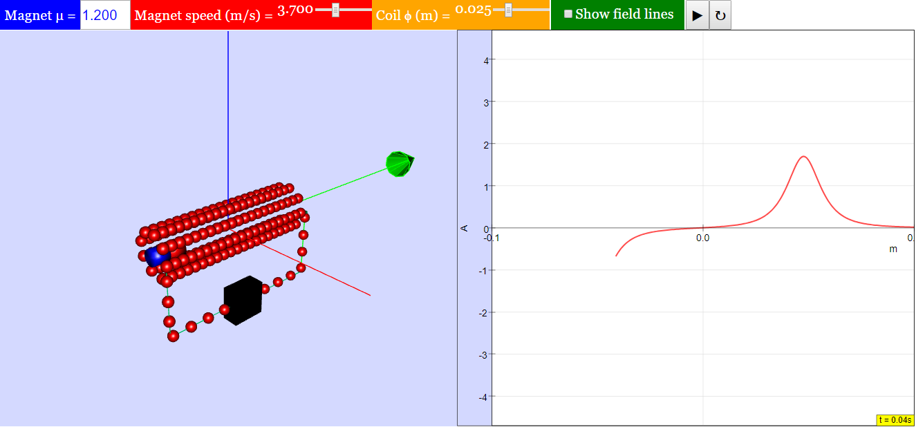
Magnet passing through a Stationary Solenoid
This simulation shows how a magnet passing through a solenoid induces an electrical current. The current is measured by the amperimeter at the right bottom of the frame.
The magnet moves with constant velocity from right to left. When it reaches the leftmost side, it stops and reverses its direction. You need to click the 'play' button again for the simulation to contin
Translations
| Code | Language | Translator | Run | |
|---|---|---|---|---|
 |
||||
Credits

 Maria Jose Cano, Jose Miguel Zamarro, Ernesto Mart’n, and Francisco Esquembre - Universidad Murcia; Fremont Teng; Jose Miguel Zamarro; Ernesto Martin; Francisco Esquembre - Universidad Murcia; Loo Kang Wee
Overview
This briefing document summarizes the key features and purpose of the "Magnet Passing Through a Stationary Solenoid JavaScript Simulation Applet HTML5" resource available on the Open Educational Resources / Open Source Physics @ Singapore website. The resource is an interactive simulation designed to illustrate the principle of electromagnetic induction, specifically how the movement of a magnet through a stationary solenoid induces an electrical current.
Main Themes and Important Ideas/Facts
- Electromagnetic Induction: The primary theme of the simulation is the phenomenon of electromagnetic induction. This fundamental concept in electromagnetism describes how a changing magnetic field through a conductor (in this case, the solenoid) induces an electromotive force (EMF), which can drive an electrical current. The simulation directly visualizes this principle.
- As stated in the "About" section, "This simulation shows how a magnet passing through a solenoid induces an electrical current."
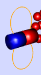
- Visualization of Magnetic Fields and Current: The simulation provides a visual representation of the magnetic field lines (orange lines around the magnet) and the induced electrical current, which is measured by an "amperimeter at the right bottom of the frame." This allows users to observe the relationship between the magnet's movement, the changing magnetic flux through the solenoid, and the resulting current.
- The "Field Lines Check Box" allows users to toggle the visibility of these field lines, aiding in understanding the magnetic field's role.
- Interactive Parameters: The applet offers several interactive elements that allow users to explore the factors influencing the induced current:
- Magnet Strength (μ): Controlled via the "Magnet μ Field Box," this setting allows users to observe how the strength of the magnetic field affects the magnitude of the induced current.
- Magnet Speed: Adjustable through the "Magnet Speed Slider," this parameter demonstrates the relationship between the rate of change of magnetic flux and the induced EMF (and thus current).
- Coil Size: The "Coil Size Slider" enables users to see how the geometry of the solenoid (likely the number of turns or the area enclosed) impacts the induced current.
- Magnet Motion: The simulation depicts the magnet moving with a "constant velocity from right to left." Upon reaching the leftmost side, it "stops and reverses its direction." This cyclical motion allows for the observation of the direction of the induced current changing as the magnetic flux through the solenoid changes in different ways (increasing, decreasing, direction of change).
- The user needs to click the "play" button to initiate or continue the simulation after the magnet reverses direction.
- Educational Resource: The resource is explicitly presented as an "Open Educational Resource" intended for learning about electromagnetism. It is part of the "MOSEM² Minds-On Physics Learning Resources," suggesting its alignment with active learning methodologies in physics education.
- The inclusion of "Sample Learning Goals" (though the actual text is not provided in the excerpt) and a section "For Teachers" further emphasizes its educational purpose.
- Technical Aspects: The simulation is a "JavaScript Simulation Applet HTML5," indicating its accessibility through web browsers without the need for additional plugins. The provision of an "Embed" code (<iframe>) highlights its usability for educators who wish to integrate the simulation into their online learning materials.
- Credits and Licensing: The resource acknowledges the contributions of several individuals from Universidad Murcia and Fremont Teng, Jose Miguel Zamarro, Ernesto Martin, Francisco Esquembre, and Loo Kang Wee for its creation. It is licensed under the "Creative Commons Attribution-Share Alike 4.0 Singapore License," promoting sharing and adaptation with proper attribution. Commercial use of the underlying "EasyJavaScriptSimulations Library" requires a separate license.
- Broader Context: The extensive list of other JavaScript simulation applets on the same website indicates a comprehensive collection of interactive resources covering various topics in physics and mathematics. This suggests that the "Magnet Passing Through a Stationary Solenoid" simulation is part of a larger initiative to provide open-source, interactive learning tools.
Key Takeaways
- The "Magnet Passing Through a Stationary Solenoid" simulation is a valuable tool for visualizing and understanding the principle of electromagnetic induction.
- Its interactive features allow users to explore the relationship between magnet properties (strength, speed), solenoid properties (size), magnetic fields, and induced current.
- The HTML5 and JavaScript implementation ensures broad accessibility for educational purposes.
- The resource is openly licensed, encouraging its use and adaptation in educational settings.
This simulation offers a hands-on, visual approach to learning about a fundamental concept in electromagnetism, making it a potentially effective tool for students and educators
Study Guide: Magnet Passing Through a Stationary Solenoid Simulation
Key Concepts
- Electromagnetic Induction: The process by which a changing magnetic field induces an electromotive force (EMF), and thus a current, in a conductor.
- Faraday's Law of Induction: The magnitude of the induced EMF in any closed circuit is equal to the time rate of change of the magnetic flux through the circuit. Mathematically, EMF = -dΦB/dt, where ΦB is the magnetic flux.
- Magnetic Flux: A measure of the total magnetic field that passes through a given area. It is defined as ΦB = B ⋅ A ⋅ cos(θ), where B is the magnetic field strength, A is the area, and θ is the angle between the magnetic field vector and the area vector.
- Lenz's Law: The direction of the induced current in a closed circuit is such that it opposes the change in magnetic flux that produces it.
- Solenoid: A coil of wire wound into a helix. When current flows through it, it creates a magnetic field similar to that of a bar magnet.
- Amperimeter: An instrument used to measure electric current in amperes.
- Magnetic Field Lines: Visual representations of a magnetic field, showing the direction and relative strength of the field. They emerge from the north pole of a magnet and enter the south pole.
Quiz
- Describe what the simulation demonstrates when a magnet passes through a stationary solenoid.
- Explain the relationship between the moving magnet and the electrical current measured by the amperimeter in the simulation.
- According to Faraday's Law, what is the primary factor that determines the magnitude of the induced EMF in the solenoid?
- How does the direction of the induced current change as the magnet moves into and then out of the solenoid? Which law explains this?
- What happens to the induced current when the magnet stops moving within the solenoid? Explain why.
- How does increasing the speed of the magnet affect the induced current in the solenoid, according to the simulation?
- What visual representation in the simulation helps to understand the magnetic field produced by the magnet?
- How does changing the strength of the magnet (using the 'Magnet μ Field Box') influence the induced current? Explain the connection.
- What role does the solenoid (coil of wire) play in the process of electromagnetic induction demonstrated by the simulation?
- What is the purpose of the 'Play/Pause and Reset' buttons in the context of observing electromagnetic induction in this simulation?
Quiz Answer Key
- The simulation demonstrates the phenomenon of electromagnetic induction, where the movement of a magnet through a stationary solenoid induces an electrical current in the solenoid. This current is then measured and displayed by the amperimeter.
- As the magnet moves through the solenoid, its changing magnetic field lines pass through the coil, causing a change in magnetic flux. This change in flux induces an electromotive force (EMF), which drives an electrical current in the solenoid, as indicated by the amperimeter.
- The primary factor determining the magnitude of the induced EMF, according to Faraday's Law, is the rate at which the magnetic flux through the solenoid changes over time. A faster change in flux results in a larger induced EMF.
- As the north pole (or south pole) of the magnet enters the solenoid, the induced current creates a magnetic field that opposes the increasing flux. When the same pole leaves the solenoid, the induced current creates a magnetic field that opposes the decreasing flux, thus the direction of the induced current reverses. Lenz's Law explains this opposition.
- When the magnet stops moving within the solenoid, the magnetic flux through the coil becomes constant. According to Faraday's Law, if there is no change in magnetic flux (dΦB/dt = 0), there will be no induced EMF and therefore no induced current in the solenoid.
- Increasing the speed of the magnet results in a faster rate of change of magnetic flux through the solenoid. According to Faraday's Law, this leads to a larger induced EMF and consequently a larger induced current.
- The orange lines around the magnet represent the magnetic field lines. These visual cues help to understand the direction and distribution of the magnetic field created by the magnet and how it interacts with the solenoid.
- Increasing the strength of the magnet (higher μ value) results in a stronger magnetic field and a greater magnetic flux passing through the solenoid. As this stronger field moves, the rate of change of magnetic flux is larger, leading to a larger induced EMF and current.
- The solenoid acts as the conductor in which the electrical current is induced. Its coils provide multiple loops through which the magnetic flux can change, enhancing the overall induced EMF compared to a single loop of wire.
- The 'Play/Pause' button allows for starting and stopping the simulation of the magnet's movement, enabling observation of the induced current under different conditions. The 'Reset' button returns the simulation to its initial state, allowing for repeated observations with different parameter settings.
Essay Format Questions
- Discuss how the visual elements of the "Magnet Passing Through a Stationary Solenoid" simulation effectively illustrate the principles of Faraday's Law of Induction and Lenz's Law. Refer specifically to the movement of the magnet, the magnetic field lines, and the reading on the amperimeter in your explanation.
- Analyze the relationship between the adjustable parameters in the simulation (magnet strength, magnet speed, coil size) and the resulting induced current in the solenoid. Explain the physical principles that underpin these relationships.
- Compare and contrast the behavior of the induced current as the north pole versus the south pole of the magnet enters and exits the solenoid. Use Lenz's Law to explain any observed differences or similarities.
- Consider the implications of electromagnetic induction, as demonstrated in this simulation, for real-world applications. Provide at least two examples of technologies that rely on this principle and briefly explain their operation in the context of the simulation.
- Evaluate the educational value of using interactive simulations, such as the "Magnet Passing Through a Stationary Solenoid" applet, for learning about abstract physics concepts like electromagnetism. What are the strengths and potential limitations of this approach?
Glossary of Key Terms
- Electromotive Force (EMF): The voltage or potential difference induced in a circuit by a changing magnetic field (or a moving conductor in a magnetic field). It is the energy provided by a battery or an induced field per unit charge.
- Induction: The process by which a changing magnetic field creates an electric field, which can then drive an electric current in a conductor.
- Magnetic Field: A region of space around a magnet or a current-carrying wire where a magnetic force can be detected. It is represented by magnetic field lines.
- Magnetic Flux Density (B): A measure of the strength of a magnetic field at a given point, often referred to as the magnetic field strength. Its SI unit is the Tesla (T).
- Polarity: The property of a magnet or an electromagnet that determines the direction of its magnetic field (north pole and south pole).
- Rate of Change: How quickly a quantity is changing with respect to time. In the context of Faraday's Law, it refers to how rapidly the magnetic flux through the circuit is increasing or decreasing.
- Simulation: A computer-based model of a real-world system or phenomenon, used for educational or exploratory purposes. In this case, it models the interaction between a moving magnet and a stationary solenoid.
- Velocity: The rate of change of an object's position with respect to time, including both its speed and direction. In the simulation, it refers to how fast and in what direction the magnet is moving.
Sample Learning Goals
[text]
For Teachers
Magnet Passing Through a Stationary Solenoid JavaScript Simulation Applet HTML5
Instructions
Magnet μ Field Box

Magnet Speed Slider
Coil Size Slider

Field Lines Check Box

Toggling Full Screen
Play/Pause and Reset Buttons

Research
[text]
Video
[text]
Version:
Other Resources
[text]
Frequently Asked Questions: Magnet Passing Through a Stationary Solenoid Simulation
1. What does this simulation demonstrate?
This simulation visually illustrates the principle of electromagnetic induction, specifically Faraday's Law. It shows how moving a magnet through a stationary solenoid (a coil of wire) induces an electrical current in the solenoid.
2. How is the induced current measured in the simulation?
The induced electrical current is measured and displayed by an amperimeter located at the bottom right of the simulation frame. The reading on the amperimeter will change as the magnetic flux through the solenoid changes due to the moving magnet.
3. What user-adjustable parameters are available in the simulation?
Users can interact with several parameters to observe their effect on the induced current. These include:
- Magnet Strength (μ Field Box): Adjusting this changes the strength of the magnetic field produced by the magnet.
- Magnet Speed Slider: This controls the velocity at which the magnet moves through the solenoid.
- Coil Size Slider: This allows modification of the physical dimensions of the solenoid.
- Field Lines Check Box: Toggling this option shows or hides the orange field lines around the magnet, providing a visual representation of the magnetic field.
4. How does the movement of the magnet relate to the induced current?
As the magnet moves through the solenoid, the magnetic flux (the amount of magnetic field passing through the coil) changes. According to Faraday's Law of induction, this changing magnetic flux induces an electromotive force (EMF), which in turn drives an electrical current in the closed loop of the solenoid. The direction and magnitude of the induced current depend on the direction and rate of change of the magnetic flux.
5. What happens when the magnet stops and reverses direction?
When the magnet reaches the leftmost side and stops, the magnetic flux through the solenoid becomes momentarily constant, and the induced current drops to zero. When the magnet reverses its direction and moves back to the right, the magnetic flux changes again, inducing a current in the opposite direction, as indicated by the amperimeter. To observe this reversed motion, the user needs to click the 'play' button again.
6. What are some suggested learning goals for using this simulation?
While specific learning goals are not explicitly detailed in the provided text, based on the simulation's features, some potential learning goals could include:
- Understanding the relationship between the motion of a magnet and the induction of current in a coil.
- Observing how changing the speed and strength of the magnet affects the magnitude and direction of the induced current.
- Investigating how the physical characteristics of the solenoid (like its size) influence the induced current.
- Visualizing magnetic field lines and their role in electromagnetic induction.
7. Is this simulation embeddable on other webpages?
Yes, the simulation can be embedded into other webpages using the provided iframe code. This allows educators and learners to integrate the interactive model into various online learning platforms and resources.
8. Who are the creators and contributors to this simulation?
The simulation was developed by Maria Jose Cano, Jose Miguel Zamarro, Ernesto Mart’n, and Francisco Esquembre from Universidad Murcia, with contributions from Fremont Teng and Loo Kang Wee. The EasyJavaScriptSimulations (Ejs) library used to create this simulation was developed by Francisco Esquembre.
- Details
- Written by Fremont
- Parent Category: 05 Electricity and Magnetism
- Category: 08 Electromagnetic Forces or Electromagnetism
- Hits: 9688