


About
Simple Ray Diagram Maker (Flat mirror)
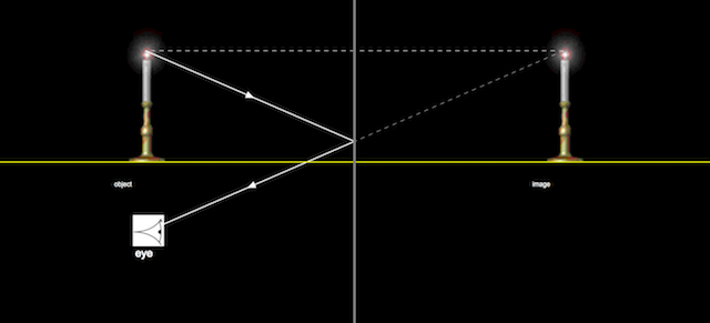
The simple ray diagram maker shows one principal ray leaving a candle of height h and striking a flat mirror. This ray strikes the mirror a distance h below the flame. The angle between the reflected ray and the surface normal is the same as that between the incident ray and the normal in accord with the principles of geometric optics.
Drag the slider that controls the position of the candle base to observe the corresponding motion of the virtual image. The simple geometry shows that the reflection of a candle placed a distance d in front of a mirror will produce a candle image that is a distance d behind the mirror.
Click on steps 1, 2, and 3 to show the procedural steps in drawing a simple ray diagram. Step 1 shows the line used to find the position of the image equidistant from the mirror as the object. Step 2 shows the ray from the image to the eye (observer). While step 3 shows the ray from the object reflecting off the mirror.
Dotted lines are used to represent virtual rays.
Dray the eye to control the position of the eye which shows how the principal ray can travel from the object reflecting off the mirror and finally reaching the eye.
Credits
The Simple Ray Diagram Maker was developed by Richmond Ang by modifying the The Flat Mirror Model developed by Wolfgang Christian, Francisco Esquembre, and Mario Belloni using the Easy Java Simulations (EJS) version 5.0 authoring and modeling tool.
About this Simulation
This interactive ray diagram simulation allows learners to visualize how light rays travel, reflect, and refract through different media and optical systems. Students can manipulate ray positions and observe real-time changes in ray paths, exploring fundamental principles of geometric optics and light behavior in an intuitive, visual environment.
Learning objectives: Understand how light rays behave at boundaries and through optical components | Apply geometric principles to predict ray paths in optical systems | Investigate the relationship between object position and ray diagram geometry
Title and author:
Simple Ray Diagram

![]()

![]() Wolfgang Christian - Davidson College; Francisco Esquembre - U. Murcia; Mario Belloni - Davidson College
Wolfgang Christian - Davidson College; Francisco Esquembre - U. Murcia; Mario Belloni - Davidson College
Translations
| Code | Language | Translator | Run | |
|---|---|---|---|---|
 |
||||
Credits
![]()

![]() Wolfgang Christian - Davidson College; Francisco Esquembre - U. Murcia; Mario Belloni - Davidson College
Wolfgang Christian - Davidson College; Francisco Esquembre - U. Murcia; Mario Belloni - Davidson College
Briefing Document: Simple Ray Diagram for Mirrors JavaScript HTML5 Applet Simulation Model
1. Overview
This document reviews a resource from the Open Educational Resources / Open Source Physics @ Singapore website, specifically a JavaScript HTML5 applet simulation model for creating simple ray diagrams for flat mirrors. The resource is designed as an interactive tool for visualizing how light reflects off a flat mirror and how an image is formed. The simulation allows users to manipulate elements and observe the resulting changes in the ray diagram.
2. Main Themes and Key Ideas
- Geometric Optics Principles: The simulation emphasizes fundamental principles of geometric optics, particularly the law of reflection, which states that the angle of incidence is equal to the angle of reflection. The applet visualizes this concept clearly with ray tracing.
- Ray Diagrams for Flat Mirrors: The core focus is on constructing ray diagrams for flat mirrors to understand image formation. The simulation specifically models a candle in front of a mirror, showing the incident ray, reflected ray, and virtual image formation.
- Virtual Image Formation: The applet clearly demonstrates that flat mirrors create virtual images, meaning that the light rays do not actually converge at the image location. Dotted lines are used in the simulation to represent these virtual rays and the position of the image.
- Image Location and Distance: The simulation shows that the image formed by a flat mirror is located at the same distance behind the mirror as the object is in front of it. The text explains, "The simple geometry shows that the reflection of a candle placed a distance d in front of a mirror will produce a candle image that is a distance d behind the mirror."
- Interactive and Visual Learning: The applet is designed to be interactive, with sliders for controlling the candle position and a draggable eye position to show how principal rays can reach an observer after reflecting off the mirror. This allows users to explore the concepts through direct manipulation and visual feedback.
- Step-by-step diagram creation: The applet has the option to "Click on steps 1, 2, and 3 to show the procedural steps in drawing a simple ray diagram."
3. Key Facts and Details
- Simulation Functionality:The simulation shows a candle in front of a flat mirror.
- Users can drag a slider to change the position of the candle's base and observe the corresponding change in the virtual image location.
- The applet illustrates how the reflected ray reaches the eye, and the user can move the eye position to view the virtual image.
- The simulation uses dotted lines for virtual rays, which reinforces understanding.
- Development Credits: The Simple Ray Diagram Maker is developed by Richmond Ang, modifying "The Flat Mirror Model" by Wolfgang Christian, Francisco Esquembre, and Mario Belloni.
- Tools Used: The model was created using Easy Java Simulations (EJS) version 5.0, which indicates a focus on open-source modeling tools.
- License: The resource is licensed under the Creative Commons Attribution-Share Alike 4.0 Singapore License, promoting open sharing and reuse of educational materials. However, commercial use of the underlying EasyJavaScriptSimulations Library requires separate permissions and contact.
- Accessibility: The resource is embeddable using an iframe, which makes it easy to incorporate into other webpages or learning platforms.
- Additional Resources: The page contains a large list of links to other physics simulations and educational resources that are all part of the Open Source Physics @ Singapore project. This indicates that this applet is part of a broader collection of resources.
4. Quotes from the Source
- "The simple ray diagram maker shows one principal ray leaving a candle of height h and striking a flat mirror. This ray strikes the mirror a distance h below the flame."
- "The angle between the reflected ray and the surface normal is the same as that between the incident ray and the normal in accord with the principles of geometric optics."
- "The simple geometry shows that the reflection of a candle placed a distance d in front of a mirror will produce a candle image that is a distance d behind the mirror."
- "Click on steps 1, 2, and 3 to show the procedural steps in drawing a simple ray diagram."
- "Dotted lines are used to represent virtual rays."
5. Implications
- Educational Tool: The simulation is designed to be an educational tool to help students understand ray diagrams and image formation with flat mirrors. Its interactive and visual nature makes learning more engaging and intuitive.
- Open Source Initiative: It is part of a larger Open Source Physics project, which aims to make high-quality educational resources available to a wide audience.
- Reusability: The Creative Commons license promotes use and modification of the tool for different learning contexts, enhancing flexibility in educational use.
6. Conclusion
The Simple Ray Diagram Maker applet is a well-designed, interactive simulation that provides a valuable tool for teaching and learning about image formation with flat mirrors. Its emphasis on geometric optics principles, visual representation, and ease of use make it an excellent educational resource that aligns well with the principles of inquiry based learning. Its open-source nature fosters collaborative education and allows it to be expanded and modified by others. The applet is one among many resources created and curated by the Open Educational Resources/Open Source Physics @ Singapore group, and provides a glimpse into their goal of making educational content accessible and engaging.
Mirrors and Ray Diagrams: A Study Guide
Quiz
Instructions: Answer the following questions in 2-3 sentences each.
- What is the purpose of the Simple Ray Diagram Maker?
- Describe the relationship between the incident ray and the reflected ray in terms of the normal.
- According to the simulation, where is the virtual image formed in relation to a flat mirror?
- What is the significance of using dotted lines in a ray diagram?
- How can the position of the observer's eye affect the ray diagram?
- What are the three procedural steps involved in drawing a simple ray diagram as shown by the simulation?
- What is the relationship between the distance of an object in front of a flat mirror and the distance of its image behind the mirror?
- Who developed the original Flat Mirror Model that the Simple Ray Diagram Maker was based on?
- What tool was used to create the Simple Ray Diagram Maker?
- In this simulation, what is the object from which the light rays are emanating?
Quiz Answer Key
- The Simple Ray Diagram Maker is designed to illustrate how light rays from an object reflect off a flat mirror to form a virtual image. It helps visualize the principles of geometric optics in the context of mirror reflections.
- The angle between the incident ray and the normal is the same as the angle between the reflected ray and the normal. The normal is a line perpendicular to the surface at the point of reflection.
- The virtual image appears to be located the same distance behind the mirror as the object is in front of the mirror. This creates a symmetrical relationship across the mirror's surface.
- Dotted lines represent virtual rays, which are not actual paths of light but rather extensions of the reflected rays. These are used to locate where the image appears to be.
- The observer's eye position dictates the direction from which the reflected ray is viewed. The ray must travel from the object, reflect off the mirror, and reach the eye to be visible.
- The procedural steps are: 1) drawing a line to find the position of the image equidistant from the mirror, 2) drawing a ray from the image to the eye, and 3) drawing a ray from the object reflecting off the mirror.
- The distance of an object in front of a flat mirror is equal to the distance of its image behind the mirror. The object and the image are always equidistant from the mirror.
- The original Flat Mirror Model was developed by Wolfgang Christian, Francisco Esquembre, and Mario Belloni. These physicists are credited with creating the foundation for this visualization.
- The Simple Ray Diagram Maker was developed using the Easy Java Simulations (EJS) version 5.0 authoring and modeling tool. This tool enables interactive simulations.
- The object in the simulation from which light rays are emanating is a candle. The simulation demonstrates how the candle and its image behave in relation to a mirror.
Essay Questions
Instructions: Answer the following essay questions in a well-developed format.
- Discuss the significance of using simulations like the Simple Ray Diagram Maker in teaching geometric optics. How do they aid understanding compared to traditional methods?
- Explain how the principles of geometric optics, as represented in the Simple Ray Diagram Maker, are applicable in real-world optical devices, such as mirrors used in telescopes or car mirrors.
- Analyze the role of virtual images in the context of flat mirrors. How do they differ from real images and why is this distinction important?
- Describe the limitations of the Simple Ray Diagram Maker, and how it could be expanded or improved to teach more complex mirror concepts.
- Relate the interactive features of the Simple Ray Diagram Maker to effective learning practices. How does the interactivity enhance student engagement and retention of information?
Glossary of Key Terms
Incident Ray: A ray of light that approaches a surface, such as a mirror.
Reflected Ray: A ray of light that is bounced off a surface, like a mirror.
Normal: A line that is perpendicular to a surface at the point where the incident ray strikes.
Virtual Image: An image formed by the apparent intersection of light rays, but no actual light rays pass through the image location, and cannot be projected on a screen; this appears to be behind a mirror.
Geometric Optics: The branch of optics that studies the behavior of light by representing it as rays, without considering its wave nature.
Ray Diagram: A visual representation that uses lines (rays) to illustrate the path of light as it interacts with optical elements, such as mirrors and lenses.
Object: The source of light rays in a ray diagram, from which light originates.
Mirror: A reflective surface that forms images through reflection, here specifically a flat mirror.
Angle of Incidence: The angle between the incident ray and the normal.
Angle of Reflection: The angle between the reflected ray and the normal.
Version
Frequently Asked Questions: Ray Diagrams and Mirror Reflections
- What is a simple ray diagram and what is its purpose? A simple ray diagram is a visual tool used to trace the path of light as it reflects off a mirror. In the context of a flat mirror, it's used to understand how an object’s image is formed. By drawing lines that represent the path of light rays, we can determine the location and properties of the virtual image. This helps us visualize how we see objects reflected in a mirror.
- How is a virtual image formed by a flat mirror, and what are its characteristics? A virtual image formed by a flat mirror is an image that appears to be behind the mirror. It is "virtual" because the light rays do not actually converge there; instead, our brains interpret the diverging reflected rays as if they originated from behind the mirror. The key characteristic of this virtual image is that it is upright, the same size as the object, and located at the same distance behind the mirror as the object is in front of the mirror. It is a mirror image, appearing as a left-right reversal of the object.
- What role does the "normal" play in drawing ray diagrams for mirror reflection? The "normal" is an imaginary line perpendicular to the surface of the mirror at the point where a light ray strikes. It serves as a reference for measuring the angles of incidence and reflection. The law of reflection states that the angle between the incident ray and the normal is equal to the angle between the reflected ray and the normal. This relationship is fundamental to accurately drawing ray diagrams.
- How does the position of the observer (eye) affect what is seen in the reflected image? The position of the observer affects which reflected rays will reach the eye, and how they are interpreted to form the perceived image. The ray diagram shows how a specific ray from an object reflects off the mirror and reaches the eye. Moving the observer's position changes the perspective, but the virtual image's characteristics – such as size, distance, and orientation – remain the same for different viewing positions.
- What do the dotted lines in a ray diagram represent? Dotted lines in a ray diagram represent virtual rays or extensions of light rays. In the context of mirrors, these lines extend backward from the reflected rays to the point where they would hypothetically intersect, thereby locating the virtual image. These lines do not represent real light rays but are used to visually trace the path of rays that appear to come from the image behind the mirror.
- What is the relationship between the object distance and the image distance in a flat mirror? For a flat mirror, the object distance (the distance from the object to the mirror) is equal to the image distance (the distance from the image to the mirror, measured behind the mirror). This relationship is a direct consequence of the laws of reflection and is a defining property of flat mirror reflections.
- How can interactive tools and simulations, like the one mentioned in the text, aid in understanding ray diagrams? Interactive tools and simulations provide a dynamic and engaging way to learn about ray diagrams. By allowing users to manipulate variables, such as the position of the object and observer, students can directly observe how these changes affect the virtual image. The simulations help visualize the geometric relationships, and make the abstract concepts more intuitive, enhancing conceptual understanding. Step by step visualizations also make it easy to see the process behind constructing a ray diagram.
- Who developed the Simple Ray Diagram Maker and what is the resource it was based on? The Simple Ray Diagram Maker was developed by Richmond Ang. It was created by modifying the Flat Mirror Model developed by Wolfgang Christian, Francisco Esquembre, and Mario Belloni using the Easy Java Simulations (EJS) version 5.0 authoring and modeling tool. It is thus derived from the original work done by these authors, further illustrating the collaborative nature of open education resources.