About
Briefing Document: EJS Ripple Tank Model
1. Introduction:
This document provides an overview of the EJS (Easy JavaScript Simulation) Ripple Tank Model, an open educational resource for teaching wave properties. The model is designed to simulate the behavior of waves in a ripple tank, a shallow tank of water used to demonstrate fundamental wave phenomena. The resource is primarily intended for use in physics education, particularly at the junior college level.
2. What is a Ripple Tank?
- A ripple tank is a shallow glass tank filled with water used to visualize wave behavior.
- It is illuminated from above (or sometimes below) and the resulting shadows of ripples are projected onto a screen.
- It enables the demonstration of basic wave properties such as reflection, refraction, interference, and diffraction.
- Ripples can be generated by a vibrating piece of wood attached to a motor with an off-center weight.
3. Key Concepts Illustrated by the EJS Ripple Tank Model
The EJS Ripple Tank model focuses specifically on two-source interference. Here are the key concepts it illustrates:
- Two-Source Interference: The model simulates two point sources (dippers) generating circular waves. When these waves meet, they interfere.
- Superposition: The waves from the two sources superpose, meaning that the displacements of the waves are added at every point.
- Constructive Interference: Occurs when waves meet in phase (peak meets peak or trough meets trough). This results in a larger amplitude wave. The model represents constructive interference with bright areas or red lines.
- Quote: "... the anti-nodes will be alternating between bright (eg. peak meet peak ) and dark ( eg. trough meet trough) for White and Black visualization or Red (eg. peak meet peak ) and Blue ( eg. trough meet trough) due to constructive interference"
- Destructive Interference: Occurs when waves meet out of phase (peak meets trough). This results in a smaller amplitude wave, potentially even canceling out completely. The model represents destructive interference with green lines or nodes.
- Quote: "The positions where the waves meet that cancel out are called nodes... destructive interference occurs (i.e. source waves arrive in anti-phase)"
- Nodes: Points of zero displacement resulting from destructive interference.
- Quote: "the green parts are called nodes where the 2 waves meet destructively to create zero displacement"
- Antinodes: Points of maximum displacement resulting from constructive interference.
- Nodal Lines: Lines connecting the nodes.
- Antinodal Lines: Lines connecting the antinodes.
- Quote: "The lines passing through a series of nodes are called the nodal lines" and "The lines passing through a series of anti-nodes are called the antinodal lines"
- Stationary Waves: A stationary wave is formed between the two sources due to constructive and destructive interference.
4. Path Difference and Interference
The model demonstrates how path difference (the difference in distance from two sources to a point) determines whether interference is constructive or destructive:
- Constructive Interference: Occurs when the path difference is a whole number multiple of the wavelength (mλ, where m = 0, 1, 2...).
- Quote: "condition for constructive interference: ∆L = m λ, where m = 0, 1, 2, ..."
- Destructive Interference: Occurs when the path difference is a half-integer multiple of the wavelength ((m + 0.5)λ, where m = 0, 1, 2...).
- Quote: "condition for destructive interference: ∆L = (m + 0.5) λ, where m = 0, 1, 2, ..."
The document includes specific examples demonstrating these calculations with the symbols S1P, S2P and wavelength λ.
5. EJS Ripple Tank Model Features
- Interactive Simulation: The EJS model provides an interactive simulation that allows students to visualize wave interference patterns.
- Embeddable: The model can be embedded in a webpage using an iframe.
- Accessible: The model is designed to run on Windows, MacOSX, and Linux, including laptops and desktops.
- Visualizations: It uses color (green, red, blue, black, and white) to differentiate between constructive and destructive interference patterns.
- Flexibility: The user can modify conditions, including the sources being in anti-phase.
6. Educational Applications (For Teachers)
- Curriculum Alignment: The model directly aligns with physics curriculum topics related to superposition, interference, and coherence. Specifically it is mentioned that "SECTION lV WAVES Superposition (f) show an understanding of the terms interference and coherence. (g) show an understanding of experiments which demonstrate two-source interference using water, light and microwaves."
- Hands-on Exploration: While virtual, it provides a hands-on experience of experimenting with wave behavior.
- Supplemental Resource: The model can be used alongside real ripple tank setups for greater understanding.
- Conceptual Understanding: The visualization and interactive nature of the simulation helps students build a stronger understanding of wave superposition.
7. Technical Details and Resources:
- Software Requirement: Requires Java.
- Real Setups: Provides links to real ripple tank setups from Wikipedia and other resources.
- Video Resource: Links to a video demonstration of a ripple tank.
- Credits: The model is credited to Andrew Duffy, Juan M. Aguirregabiria, Fu-Kwun Hwang, and Loo Kang Wee.
- Various versions of the model: multiple java versions and modifications by different authors are available at the provided links
8. Related Resources:
The document includes links to other related simulations, applets and online resources such as:
- PhET Wave Interference Simulation
- GeoGebra models
- Online applet collections
9. Key Takeaways
- The EJS Ripple Tank Model is a valuable open educational resource for teaching wave interference.
- It provides interactive and visual simulations of key concepts, making it easier for students to understand.
- The model is designed to complement traditional instruction and real ripple tank experiments.
10. Additional Notes: The document is very comprehensive, including even details about specific file names and timestamps for images related to the model. It also mentions authors and contributors, licensing details, and even details for contact for commercial usage of certain tools. It also includes a large list of other available simulations from the same source.
Ripple Tank Model Study Guide
Quiz
Instructions: Answer the following questions in 2-3 sentences each.
- What is a ripple tank and what is its primary function in physics education?
- How are ripples generated in a typical ripple tank setup?
- Describe the phenomenon of superposition as it applies to waves in a ripple tank.
- Explain the difference between constructive and destructive interference in the context of ripple tank waves.
- What are nodes and how do they appear in an interference pattern?
- What are antinodes and how do they appear in an interference pattern?
- What are nodal lines, and how do they relate to wave interference?
- What are antinodal lines, and how do they relate to wave interference?
- If the path difference between two waves is a whole number of wavelengths, will constructive or destructive interference occur? Explain.
- If the path difference between two waves is a half-integer number of wavelengths, will constructive or destructive interference occur? Explain.
Quiz Answer Key
- A ripple tank is a shallow glass tank of water used to demonstrate the basic properties of waves. Its main function is to visualize wave phenomena like reflection, refraction, interference, and diffraction.
- Ripples are typically generated by a motor with an off-center weight attached to a wooden piece that is touching the surface of the water. As the motor rotates, it shakes the wood, creating waves in the water.
- Superposition is when two or more waves meet, and their displacements combine to form a resultant wave. In a ripple tank, this can result in areas of constructive or destructive interference.
- Constructive interference occurs when waves meet in phase, resulting in a larger amplitude wave (e.g., peak meets peak, trough meets trough). Destructive interference occurs when waves meet out of phase, resulting in a smaller amplitude or zero amplitude wave (e.g., peak meets trough).
- Nodes are points in the interference pattern where destructive interference occurs and the waves cancel out. In a ripple tank, they appear as locations of minimal or no displacement, often appearing dark.
- Antinodes are points in the interference pattern where constructive interference occurs, leading to a larger amplitude. In a ripple tank, they will appear as the brightest (peak meets peak) or darkest (trough meets trough) places in the image.
- Nodal lines are lines that connect a series of nodes, representing locations of destructive interference. They indicate areas where the waves tend to cancel each other out.
- Antinodal lines are lines that connect a series of antinodes, representing locations of constructive interference. These lines show areas of the greatest displacement in the wave pattern.
- If the path difference is a whole number of wavelengths, constructive interference occurs because the waves arrive in phase. They will have a peak meet a peak or a trough meet a trough.
- If the path difference is a half-integer number of wavelengths, destructive interference occurs because the waves arrive in anti-phase. A peak of one wave will meet a trough of another wave.
Essay Questions
Instructions: Answer the following questions in essay format, using your understanding of the ripple tank model and wave interference.
- Explain how a ripple tank demonstrates the principles of wave superposition and interference. Discuss both constructive and destructive interference, and include the role of path difference.
- Describe the ripple tank setup, including how the waves are generated and how the interference pattern is visualized. Then, describe how changing the frequency of the vibrator would affect the observed interference patterns.
- Compare and contrast the concepts of nodes and antinodes in the context of wave interference. Explain how they are formed and how they are visually represented in a ripple tank.
- Discuss how the ripple tank model can be used to understand interference phenomena in other types of waves, such as light or sound waves, and provide examples to support your claim.
- How can real-world applications of wave interference be used to discuss the educational value of the ripple tank?
Glossary of Key Terms
- Ripple Tank: A shallow glass tank of water used to demonstrate wave properties, such as superposition and interference.
- Superposition: The principle that when two or more waves overlap, the resulting wave is the sum of their individual displacements.
- Constructive Interference: When two or more waves combine in phase (peak meets peak, trough meets trough), resulting in a larger amplitude wave.
- Destructive Interference: When two or more waves combine out of phase (peak meets trough), resulting in a smaller amplitude or zero amplitude wave.
- Node: A point in an interference pattern where destructive interference occurs, resulting in minimal or zero displacement.
- Antinode: A point in an interference pattern where constructive interference occurs, resulting in maximum displacement.
- Nodal Line: A line connecting a series of nodes in an interference pattern, indicating areas of destructive interference.
- Antinodal Line: A line connecting a series of antinodes in an interference pattern, indicating areas of constructive interference.
- Path Difference: The difference in distance traveled by two waves from their sources to a specific point. The difference dictates the type of interference that will occur at that point.
- Wavelength (λ): The distance between two successive crests or troughs of a wave.
In physics and engineering, a ripple tank is a shallow glass tank of water used in schools and colleges to demonstrate the basic properties of waves. It is a specialized form of a wave tank. The ripple tank is usually illuminated from above, so that the light shines through the water. Some small ripple tanks fit onto the top of an overhead projector, i.e. they are illuminated from below. The ripples on the water show up as shadows on the screen underneath the tank. All the basic properties of waves, including reflection, refraction,interference and diffraction, can be demonstrated.
Ripples may be generated by a piece of wood that is suspended above the tank on elastic bands so that it is just touching the surface. Screwed to wood is a motor that has an off centre weight attached to the axle. As the axle rotates the motor wobbles, shaking the wood and generating ripples.
What is a Two-Source Interference (Ripple Tank)?
An example of two-source interference can be observed in a ripple tank.
 |
| (Fig. 1) Two dippers S1 and S2 are attached to the vibrator of the ripple tank. |
1. Two dippers S1 and S2 are attached to the vibrator of the ripple tank. (Fig. 1)
2. Each dipper, when oscillates vertically, generates circular waves. (Fig. 2)
 |
| Fig. 2 show Source S1 that creates a circular waves |
 |
| Fig. 2 show Source S2 that creates a circular waves |
3. When the two waves meet, they interfere where each dipper's generated circular waves which superposition with one another.
 |
| resultant wave form due to the superposition of each wave generated by S1 and S2. |
1 to 3 in animation would look like this.
 |
| Source S1 that creates a circular waves |
 |
| Source S2 that creates a circular waves |
 |
| resultant wave form due to the superposition of each wave generated by S1 and S2 |
4. Between the two dippers, a stationary wave is formed due to constructive and destructive interference
 |
| stationary wave is formed in between S1 and S2 |
 |
| stationary wave is formed in between S1 and S2 (look closely at the wave formation in between S1 and S2 |
5. When normal white light shines on the ripple tank with the interference pattern
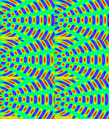
6. The positions where the waves meet that cancel out are called nodes, it is rather difficult to see so i will explain in terms of a spectrum visualization as always green due to (eg. peak meet trough) destructive interference occurs (i.e. source waves arrive in anti-phase)
 |
| the green parts are called nodes where the 2 waves meet destructively to create zero displacement |
7. The anti-nodes will be alternating between bright (eg. peak meet peak ) and dark (eg. trough meet trough) for White and Black visualization or Red (eg. peak meet peak ) and Blue (eg. trough meet trough) due to constructive interference (i.e. source waves arrive in phase). note that (peak meet peak ) and (trough meet trough) is constructive.
8. The lines passing through a series of nodes are called the nodal lines
 |
| nodal lines and antinodal lines picture by leongster |
9. The lines passing through a series of anti-nodes are called the antinodal lines
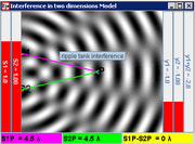
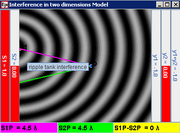
10. for example, the distance between point P and S1, S1P = 4.5 λ and S2P = 4.5 λ, therefore path difference between the sources, S2P –S1P = 0 for a constructive (trough meet trough) dark interference.
 |
| S1P = 4.5 λ |
 |
| S2P = 4.5 λ |
 |
| S2P –S1P = 0. |
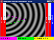
11. for example, the distance between point P and S1, S1P = 4.0 λ and S2P = 4.0 λ, therefore path difference between the sources, S2P –S1P = 0 for a constructive (peak meet peak) bright interference.
 |
| S1P = 4.0 λ |
 |
| S2P = 4.0 λ |
 |
| S2P –S1P = 0 |
12. for example, the distance between point P and S1, S1P = 5.0 λ and S2P = 5.5 λ, therefore path difference between the sources, S2P –S1P = 0.5 λ for a destructive interference.
 |
| S1P = 5.0 λ |
 |
| S2P = 5.5 λ |
 |
| |S1P –S2P| = 0.5 λ |
13. for example, the distance between point P and S1, S1P = 4.5 λ and S2P = 5.0 λ, therefore path difference between the sources, S2P –S1P = 0.5 λ for a destructive interference.
 |
| S1P = 4.5 λ |
 |
| S2P = 5.0 λ |
 |
| |S1P –S2P| = 0.5 λ |
In Conclusion, when the sources are in phase
condition for constructive interference: ∆L = m λ, where m = 0, 1, 2, ...
condition for destructive interference: ∆L = (m + 0.5) λ, where m = 0, 1, 2, ...
You can explore the applet for the cases when the sources are in anti-phase yourself !
For Teachers
https://sites.google.com/site/ijcsuperposition/
http://www.seab.gov.sg/aLevel/20102011Syllabus/9646_2011.pdf
SECTION lV WAVES Superposition
(f) show an understanding of the terms interference and coherence.
(g) show an understanding of experiments which demonstrate two-source interference using water, light and microwaves.
Software Requirements
Java
Real Setup
http://en.wikipedia.org/wiki/Ripple_tank
 |
| http://en.wikipedia.org/wiki/File:Simple_ripple_tank.svg#globalusage by Cryonic07 |
 |
| A small 650W incandescent light source was mounted about one meter above the tank, and the ripples projected on the screen were photographed from the side (see lower picture on the right) using a high-speed video camera from http://livephoto.rit.edu/LPVideos/ripple/. |
http://livephoto.rit.edu/LPVideos/ripple/Ripple_Tank_Waves_1.mov
a video suitable for video analysis using tracker?
Credits
Andrew Duffy, Juan M. Aguirregabiria, Fu-Kwun Hwang and Loo Kang Wee
Video
Physics Lab Demo 14: Ripple Tank by CarletonPhysics
Version
- http://iwant2study.org/lookangejss/04waves_11superposition/ejs/ejs_model_Ripple_Tank_Interferencewee13.jar Java Model by Andrew Duffy, Juan M. Aguirregabiria, Fu-Kwun Hwang and Loo Kang Wee
- http://weelookang.blogspot.sg/2011/01/ejs-open-source-ripple-tank.html Java version
- http://www.phy.ntnu.edu.tw/ntnujava/index.php?topic=2067.0 NTNU Java Forum by Loo Kang Wee
- http://www.compadre.org/osp/items/detail.cfm?ID=9989 Interference Model: Ripple Tank written by Andrew Duffy Original
- Juan M. Aguirregabiria for his screen patterns codes instantaneous patterns and average intensity patterns
Other resources
- ther great simulation is http://phet.colorado.edu/en/simulation/wave-interference http://phet.colorado.edu/en/simulation/wave-interference
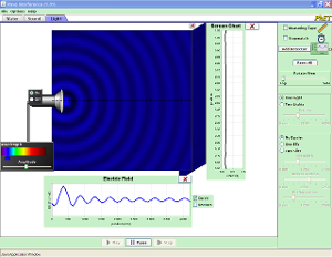 Like: a lot of possibilities very complex and realistic
 - http://www.cabrillo.edu/~jmccullough/Physics/Interference_Wave_Nature.html collection of good applets
- https://www.geogebra.org/m/XdW2SjQ8 by ukukuku
Wikipedia
Frequently Asked Questions about Ripple Tank Models
- What is a ripple tank, and how does it demonstrate wave properties? A ripple tank is a shallow glass tank filled with water, used to visualize wave phenomena. It's illuminated from above (or sometimes below), projecting shadows of the water ripples onto a screen underneath or on top. This setup allows for the clear observation and study of wave properties, such as reflection, refraction, interference, and diffraction. The ripples are typically generated by a vibrating object touching the water's surface.
- How are ripples generated in a ripple tank, and what's the role of the motor? Ripples are created using a piece of wood that's suspended on elastic bands and just touches the surface of the water. A motor with an off-center weight is attached to the wood. As the motor rotates, it wobbles, shaking the wood, which then generates ripples on the water's surface. This system provides a controllable way to produce waves in the tank.
- What is two-source interference, and how is it demonstrated in a ripple tank? Two-source interference is when waves from two different sources overlap. In a ripple tank, this can be demonstrated by attaching two dippers to the vibrator, each creating circular waves. When these waves meet, they superpose, leading to regions of constructive interference (where waves add up) and destructive interference (where waves cancel out). This overlapping of waves creates an interference pattern.
- What are nodes and antinodes in the context of ripple tank interference? In the interference pattern created by two wave sources, nodes are the points where the waves cancel each other out due to destructive interference, resulting in minimal displacement or "still water" at that location. Antinodes, on the other hand, are points where the waves reinforce each other through constructive interference, resulting in maximum displacement or the largest waves.
- What are nodal lines and antinodal lines, and how do they appear in the ripple tank? Nodal lines are lines passing through a series of nodes. These appear as darker or calmer regions in the ripple tank. Conversely, antinodal lines are lines passing through a series of antinodes, where constructive interference occurs. These are visible as brighter or regions with higher waves. In a visual representation, these can be seen as alternating dark and bright lines respectively, when illuminated.
- How can path difference be used to determine constructive and destructive interference in a two-source interference setup? Path difference refers to the difference in the distances from a given point to each of the two wave sources. For constructive interference, the path difference (ΔL) is a whole number of wavelengths (mλ, where m = 0, 1, 2...), meaning peaks align with peaks or troughs align with troughs. For destructive interference, the path difference is a half-integer multiple of wavelengths ((m + 0.5)λ, where m = 0, 1, 2...), meaning a peak from one wave aligns with a trough from another.
- What are some of the software resources available for exploring wave interference through simulation, beyond a physical ripple tank? Several software resources are available for simulating wave interference. Some of the resources mentioned include the EJS Ripple Tank Model, which runs on Java, the PHET Wave Interference simulation, a variety of applets on Cabrillo College website, and resources built with GeoGebra. These simulations allow for interactive experimentation with wave properties and interference patterns.
- What are some practical applications or extensions of the concepts learned with a ripple tank? The principles learned using a ripple tank are applicable to a variety of wave phenomena, such as light waves, sound waves and radio waves. These concepts have applications in designing concert halls for proper acoustics, developing technologies such as medical imaging and radar systems that use electromagnetic waves, and understanding complex natural phenomena like seismic waves in earthquakes or ocean tides.


