
About
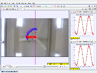
Tracker Modeling in Uniform Circular Motion of Fan
For Teachers
- Rotating fan.mp4
- Worksheet-BT Workshop.doc
Credits
Author: lookang model, jitning video
Contact: This email address is being protected from spambots. You need JavaScript enabled to view it.
Document Brief: Uniform Circular Motion Analysis Using Tracker Software
This document provides an overview of the physics principles and methodologies applied to analyze the uniform circular motion of a fan blade using Tracker, a free video analysis and modeling tool. The experiment examines the relationship between angular displacement, velocity, and acceleration, visualizing these parameters in synchronized graphs and a recorded video.
Purpose:
To help students and educators understand uniform circular motion by interpreting tracked motion data and visual representations.
Key Features:
- Analysis of position vs. time and velocity vs. time graphs.
- Visualization of circular motion using plotted trajectories.
- Detailed measurements for angular velocity and linear displacement.
- Synchronized motion with corresponding graphical data.
Study Guide: Understanding Uniform Circular Motion Using Tracker
Learning Objectives:
- Understand the concept of uniform circular motion and its defining parameters.
- Analyze motion data to determine angular velocity, frequency, and period.
- Learn how to interpret position and velocity graphs for circular motion.
Step-by-Step Guide:
-
Setup and Recording:
- Use Tracker to import the video of a fan blade in motion.
- Establish a coordinate system for tracking the motion (as shown in the purple grid).
-
Tracking Motion:
- Identify a fixed point on the fan blade and use the Tracker software to record its motion frame by frame.
- Observe the blue trajectory and red plotted data in the interface.
-
Graph Analysis:
- Examine the x-position vs. time graph to visualize sinusoidal motion due to projection.
- Look at the y-position vs. time graph, which remains constant if motion is horizontal.
- Identify the period (T) and amplitude of the sine wave to calculate angular velocity using ω=2πT\omega = \frac{2\pi}{T}.
-
Applications:
- Calculate linear velocity using v=rωv = r\omega, where rr is the radius of the circular path.
- Compare experimental data with theoretical predictions.
Tips for Success:
- Ensure proper calibration of the Tracker coordinate system to maintain data accuracy.
- Cross-check measured data points with real-time video motion for validation.
FAQ: Uniform Circular Motion Analysis
1. What is uniform circular motion?
Uniform circular motion occurs when an object moves in a circle at a constant speed. The velocity changes direction continuously, creating centripetal acceleration.
2. Why does the x-position graph look sinusoidal?
The sinusoidal graph reflects the projection of circular motion onto the x-axis, illustrating harmonic motion over time.
3. How is angular velocity calculated?
Angular velocity (ω\omega) can be calculated using the equation ω=2πT\omega = \frac{2\pi}{T}, where TT is the time period obtained from the graph.
4. Can I analyze vertical motion?
Yes. If the circular motion involves a vertical component, Tracker will show variations in the y-position graph as well.
5. What are the limitations of Tracker?
- Calibration errors can affect measurement accuracy.
- Limited frame rate of the video may lead to missing finer motion details.
6. How does this apply to real-world scenarios?
Uniform circular motion principles are foundational in understanding planetary orbits, mechanical rotors, and vehicle dynamics in curved paths.
- Details
- Parent Category: 02 Newtonian Mechanics
- Category: 05 Circle
- Hits: 8594
