About
Path of a charged particle in a homogeneous electromagnetic field
This simulation shows the path of a charged particle in a three dimensional homogeneous field, that may have electric and magnetic components. All values are normalized to a maximum of 1.
The 3D perspective projection of the path can be tilted and shifted into any direction by drawing with the mouse. The context menu (right mouse button) leads to the Camera, which allows selection of specific views.
At default a homogenous magnetic field of value 1 is oriented along the x axis. There is no electric field. The electron, initially positioned at the origin, starts with an initial velocity vector in the z direction of value 1/2. With these initial conditions it will follow a circular path around an axis parallel to that of the magnetic field (x axis). The vector of the magnetic field is shown as a thick, red arrow.
At the right side of the window a number of sliders are positioned, which determine the vectors of velocity (v), electric (E) and magnetic (B) field. In default vy and vz change periodically while the electron revolves in the yz-plane.
When electric field components are chosen by means of the corresponding sliders, the electric field vector is shown as a green arrow.
The simulation can be stopped and started with a start/stop button. Reset leads back to the default situation and stops the movement (calculation). ResetObject repositions the electron to the origin, while leaving all parameters, and the old orbit visible. ResetObject is initiated automatically when the object leaves the coordinate range. Clear deletes all orbits.
Field components can be varied while the electron is orbiting. During orbiting only zero components of the velocity vector should be changed, if one wants to arrive at easily interpretable results (e.g. vx at default)..
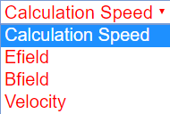
Slider speed of calculation defines the time interval of calculation and thus influences the demonstrated speed of movement.
Formulas and movement pattern
The influence of the various parameters on the movement path of a charged particle as an electron can be quite "tricky".
On should reflect wll on what one sees. Some hints:
No magnetic and electric field: the particle will simply follow its initial velocity vector. Its acceleration is zero.
Electric field only: The electric field vector determines acceleration
AccelerationEx ≈ Ex
With constant electric field a particle has constant acceleration in direction of the electric field vector. Its velocity will increase linearly.
Magnetic field only: The acceleration vector is determined by the vector product of velocity vector and magnetic field vector. It is perpendicular to the plane of both vectors. Its value is proportional to the sine of the angle between the velocity vector and the field vector.
AccelerationBx = (v x B )x ≈ (vyBz - vzBy)
A charge at rest (vy = 0; vz = 0) will not be influenced by the magnetic field, as is one which is moving in the direction of the magnetic field (sin... =0)
When the velocity vector is oblique to the field vector, the particle path will be a screw of constant pitch around an axis parallel to the magnetic field vector. When the velocity vector is perpendicular to the magnetic field vector, the path will be a circle in a plane perpendicular to the field vector.
Both electric and magnetic field: The accelerations add. In general one will get a screw path with increasing or decreasing pitch:
Acceleration(B&E)x = ≈ Ex+(vyBz - vzBy)
Acceleration(B&E)y = ≈ Ey+(vzBx - vxBz)
Acceleration(B&E)z = ≈ Ez+(vzBx - vxBz)
The following observation is quite surprising: with an electric field perpendicular to the magnetic field the particle seems to circle around the magnetic field vector, but is slowly wandering perpendicular to the electric field vector. One should recognize that in this case the particle is accelerated by the electric field during one half revolution and decelerated in the second one. It is not really moving in a circle!
In all experiments rotate the 3D projection and study the
movement
under different angles of view.
E 1: Start with the default setting and add a positive or negative velocity component vx with its slider. Try to keep the particle within the range of view by operating the slider. Try to stabilize the particle; What is the proper value of vx?
E 2: After reset add an electric field Ex. Try to stabilize the path by adjusting Ex. What is the difference to E1?
E 3: After reset draw the particle to some other point and repeat the experiments E1 and E2. Explain the result.
E 4: Try the same experiment for different axis orientations of the screw. Set proper vector components after reset and then press start.
E 5: Add other magnetic field components and analyze the result.
E 6: After reset add an electric field component perpendicular to the magnetic field and start. In which direction seems the axis of revolution to move? Why?
E 7: Define arbitrary vectors and try to interpret the results.
Translations
| Code | Language | Translator | Run | |
|---|---|---|---|---|
 |
||||
Credits
 Dieter Roess - WEH- Foundation; Fremont Teng; Loo Kang Wee
Sample Learning Goals
[text]
For Teachers
Path of a Charged Particle in a Homogeneous Electromagnetic Field JavaScript Simulation Applet HTML5
Instructions
Combo Box and Functions
Toggling Full Screen
Play/Pause, Initialise and Reset Buttons
Research
[text]
Video
[text]
Version:
Other Resources
[text]
end faq
{accordionfaq faqid=accordion4 faqclass="lightnessfaq defaulticon headerbackground headerborder contentbackground contentborder round5"}
- Details
- Written by Fremont
- Parent Category: Pure Mathematics
- Category: 3 Vectors
- Hits: 4383


.png
)


