


Credits
 [This email address is being protected from spambots. You need JavaScript enabled to view it.', 'Francisco Esquembre', 'Felix J. Garcia Clemente']
Sample Learning Goals

Educational Simulation for 555 Timer Circuit Using Easy JavaScript Simulation Toolkit
This educational simulation is designed to help students and hobbyists understand the behavior of the 555 timer IC in various configurations. Developed using the Easy JavaScript Simulation (EJS) toolkit, this simulator provides an interactive and visual way to explore and manipulate the 555 timer circuit parameters. Here are some of the features that make this simulator an effective educational tool:
Key Features
-
Interactive Parameter Adjustment:
- The simulation includes sliding bars for adjusting the values of key components in the 555 timer circuit: http://www.w3.org/1998/Math/MathML"}" data-original-tag="MATH">C1, http://www.w3.org/1998/Math/MathML"}" data-original-tag="MATH">R1, and http://www.w3.org/1998/Math/MathML"}" data-original-tag="MATH">R2
- These sliders allow users to experiment with different configurations easily and observe how changes in component values affect the circuit's behavior.
- The simulation includes sliding bars for adjusting the values of key components in the 555 timer circuit: http://www.w3.org/1998/Math/MathML"}" data-original-tag="MATH">C1, http://www.w3.org/1998/Math/MathML"}" data-original-tag="MATH">R1, and http://www.w3.org/1998/Math/MathML"}" data-original-tag="MATH">R2
-
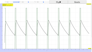
Real-time Visualization:
- The simulator provides real-time plotting of capacitor voltage and output data, which helps users visualize the charging and discharging cycles of the capacitor in the circuit.
- This immediate feedback is crucial for understanding the timing characteristics of the 555 timer.
-
Circuit Diagram Integration:
- A clear and detailed circuit diagram is included, showing the connections and components of the 555 timer circuit.
- This helps users understand the physical layout of the circuit and how different components interact with each other.
-
Reset Control:
- The simulation allows users to toggle the 555 timer's reset state between http://www.w3.org/1998/Math/MathML"}" data-original-tag="MATH">Vcc and ground using the "Reset: Vcc" button.
- This feature demonstrates the effect of the reset pin on the timer's operation, providing a hands-on way to learn about this important functionality.
-
Initial Cycle Ignorance:
- The simulation advises users to ignore the first output cycle as it depends on the initial charge of http://www.w3.org/1998/Math/MathML"}" data-original-tag="MATH">C1.
- This guidance ensures that subsequent cycles accurately represent the circuit's behavior based on the adjusted settings, leading to more reliable observations.
-
Educational Instructions:
- Clear instructions are provided on how to use the sliding bars and control the reset state, making the simulator user-friendly and accessible to beginners.
- The instructions also explain the importance of ignoring the first cycle, which helps users focus on the meaningful data produced in the simulation.

Benefits of the Simulation
- Hands-on Learning: By adjusting parameters and observing the results in real-time, users gain a practical understanding of how the 555 timer operates in different configurations.
- Visual Reinforcement: The graphical representation of voltage and output data reinforces theoretical concepts, making it easier to grasp the timing and oscillatory behavior of the 555 timer.
- Experimentation: Users can experiment with a wide range of component values without the need for physical components, saving time and resources while providing a safe learning environment.
- Conceptual Clarity: The integration of the circuit diagram with the simulation helps users correlate theoretical circuit diagrams with practical behavior, enhancing overall comprehension.
Conclusion
This 555 timer circuit simulation is a valuable educational tool that leverages the capabilities of the Easy JavaScript Simulation toolkit to provide an interactive and engaging learning experience. By combining real-time visualization, interactive parameter adjustment, and clear educational guidance, the simulator effectively helps users understand the complexities of the 555 timer IC and its applications in electronic circuits.
For Teachers
20240718-24 Web EJS beta Workshop by Francisco Esquembre and Félix J. García Clemente supported by MOE CPDD1 Registration for Web EJS Workshop (18-24 July 2024)
Venue: MOEHQ Buona Vista, B3-02 (18 July) P2-01-02 (19,22,23,24 July) or
Contact organisers at This email address is being protected from spambots. You need JavaScript enabled to view it. and/or This email address is being protected from spambots. You need JavaScript enabled to view it.
Research
[text]
Video
[text]
Version:
- https://weelookang.blogspot.com/2024/03/20240718-24-web-ejs-beta-workshop-by.html?m=1
- https://weelookang.blogspot.com/2024/07/project-1-webejs-workshop-game-for.html
Other Resources
[text]
end faq
{accordionfaq faqid=accordion4 faqclass="lightnessfaq defaulticon headerbackground headerborder contentbackground contentborder round5"}
- Details
- Written by Loo Kang Wee
- Parent Category: Sciences
- Category: Design and Technology
- Hits: 3483