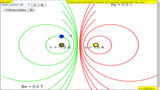
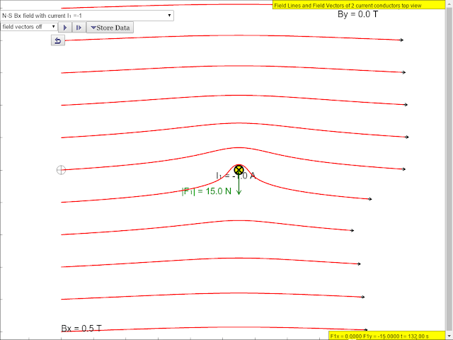
About
Magnetic field of the 2 wire currents in a external Bx
magnetic field
Magnetic Field from 2 wires
The EJS Magnetic Field from 2 wires model computes the B-field created by an electric current through 2 straight wires in the z direction with the options of external magnetic fields. The user can click on any part of the 2D space to plot the magnetic field lines.
- Watch the simulation as the field changes from the field around a long straight current-carrying wire to the field near a coil. Explain what happens to the field. Inside a coil of many loops, why is the field fairly uniform near the center (think about vector addition and what vectors would be adding together near the center).
- There is an arrow on each end of the wire (red and blue). Which one shows the direction of the current in the wire? Explain.
- The simulation also shows the magnetic flux. What is flux? Therefore, what do the different colors represent and why (i.e is pink higher flux than yellow or vice versa)? and what does "higher flux" mean in terms of the geometry and field strength?)?
Credits:
The Magnetic Field from Loops simulation was created by Fu-Kwun Hwang, edited by Loo Kang WEE using the Easy Java Simulations (EJS) modeling tool . Additional exercises written by Loo Kang WEE. You can examine and modify the model for this simulation if you have Ejs installed by right-clicking within the simulation frame and selecting "Open Ejs Model" from the pop-up menu. Information about EJS is available at: <http://www.um.es/fem/Ejs/> and in the OSP ComPADRE collection <http://www.compadre.org/OSP/>.
Translations
| Code | Language | Translator | Run | |
|---|---|---|---|---|
 |
||||
Credits

 Fu-Kwun Hwang - Dept. of Physics, National Taiwan Normal Univ. and lookang; Loo Kang Wee
Briefing Document: Magnetic Field of 2 Current-Carrying Wires Simulation
1. Overview
This document reviews a simulation tool designed to visualize the magnetic field generated by two current-carrying wires. The simulation, created using Easy Java Simulations (EJS), is available as a JavaScript HTML5 applet, making it accessible across various platforms (desktops, laptops, tablets, smartphones). The tool is intended for educational purposes, specifically for students studying electromagnetism at the secondary and junior college level. The simulation allows users to explore how the magnetic field changes based on the direction and magnitude of current in each wire, and the presence of an external magnetic field.
2. Main Themes and Important Ideas
- Visualization of Magnetic Fields: The core function of the simulation is to visually represent magnetic fields. It depicts the field lines created by the current-carrying wires in 2D space. Users can click on any part of the space to view the magnetic field lines.
- Effect of Current on Magnetic Field: The simulation allows students to observe how changing the current in the wires (direction and magnitude) alters the magnetic field pattern. By manipulating the current, the simulation demonstrates the transformation from the field of a single straight wire to that of a coil (or a more complex field).
- Superposition of Magnetic Fields: The simulation helps visualize the principle of superposition of magnetic fields, showing how the fields from the two wires combine to form a resultant field. This includes the concept of vector addition, which is particularly important when considering the field at the center of a coil. The description says, "Inside a coil of many loops, why is the field fairly uniform near the center (think about vector addition and what vectors would be adding together near the center)."
- External Magnetic Field Influence: The simulation can also include an external magnetic field (Bx), allowing students to observe how the external field interacts with the fields produced by the wires. This shows that “the yellow resultant field lines that will result in force on wire1 to be down in the negative y direction, force on wire 2, force is positive y direction as the yellow field lines suggests closer separation at the top of wire 1 and bottom of wire 2."
- Magnetic Flux: The simulation illustrates the concept of magnetic flux. Different colors are used to represent varying levels of flux, with the description prompting: "what do the different colors represent and why (i.e is pink higher flux than yellow or vice versa)? and what does "higher flux" mean in terms of the geometry and field strength?)?". This connects the visualization to a more quantitative measure of magnetic fields.
3. Key Features & Functionality
- Interactive Simulation: Users can actively interact with the simulation by:
- Changing the current in each wire (I1, I2) with values like -1A, or 1A.
- Introducing an external magnetic field Bx with a value like 0.5T.
- Clicking on any part of the 2D space to plot field lines.
- Visual Representations:Field lines are shown in 2D space, helping users visualize the direction and strength of the magnetic field.
- Color-coded representation of magnetic flux, which offers a qualitative perspective.
- Focus Questions: The simulation includes specific focus questions to guide student learning such as:
- "Watch the simulation as the field changes from the field around a long straight current-carrying wire to the field near a coil. Explain what happens to the field."
- "There is an arrow on each end of the wire (red and blue). Which one shows the direction of the current in the wire? Explain."
- Flexibility and Access: The simulation is built using HTML5 and JavaScript, allowing it to be embedded in webpages and used across a variety of devices. Additionally, there are links to apps on Google Play and the Apple app store, allowing for mobile access.
- Open Source: The simulation model can be examined and modified by those who have EJS installed, promoting its use and adaptation. It can be accessed by "right-clicking within the simulation frame and selecting "Open Ejs Model" from the pop-up menu".
- Supplementary Resources: The webpage contains links to other resources and simulations related to electromagnetism. This includes external sites with relevant animations. For example, there is a link to "http://web.mit.edu/8.02t/www/802TEAL3D/teal_tour.htm Magnetostatics: found this fantastic graphics for An animation of the magnetic field and forces generated by two parallel wires is visualized when the current in the wires run in opposite directions." There is also a link to a Youtube video, "Electromagnetism (part 2): Working Principles of a DC Motor by ETDtogo."
4. Learning Goals
The simulation aims to help students understand:
- The relationship between electric current and magnetic fields.
- How magnetic fields from multiple sources interact and combine.
- The concept of magnetic flux.
- The visual representation of magnetic fields.
- How external magnetic fields influence the magnetic fields created by wires.
5. Target Audience
- Secondary and Junior College students studying electromagnetism.
- Physics teachers who may use the simulation to enhance instruction.
6. Credits
The simulation was developed by Fu-Kwun Hwang and Loo Kang Wee, using the Easy Java Simulations tool.
7. Sample Learning Scenarios
The page offers examples of what can be simulated, for instance: * current I1 = -1A, I2 = 1A * external magnetic field Bx =0.5T * external magnetic field Bx =0.5T ,current I1 = -1A, I2 = 1A, showing the yellow resultant field lines that will result in force on wire1 to be down in the negative y direction, force on wire 2, force is positive y direction as the yellow field lines suggests closer separation at the top of wire 1 and bottom of wire 2.
8. Conclusion
The "Magnetic Field of 2 Current Conducting Wires" simulation is a valuable educational tool for visualizing and understanding key concepts in electromagnetism. Its interactive nature, combined with visual representation and focus questions, makes it a beneficial resource for both students and educators.
Magnetic Field of Two Current-Carrying Wires: A Study Guide
Quiz
Answer the following questions in 2-3 sentences each.
- How does the magnetic field change as you transition from a single long straight wire to a coil of many loops?
- In the simulation, which colored arrow indicates the direction of the electric current in the wire and why?
- What is magnetic flux, and what do the different colors represent in terms of flux levels in the simulation?
- According to the simulation description, why is the magnetic field fairly uniform near the center of a coil?
- What are some of the example scenarios that can be simulated using the model provided in the resource?
- If the wires are carrying current in the opposite direction, how would the resulting magnetic field affect the wires?
- What does it mean when the simulation mentions that the yellow field lines suggest "closer separation"?
- What is Easy Java Simulations (EJS) and where can you find more information about it?
- According to the "About" section, what does this simulation model compute?
- Besides the website, what are other ways you can access this simulation?
Answer Key
- The magnetic field transitions from circular field lines around a single wire to a more concentrated and stronger field within the coil. The field becomes more uniform inside the coil due to the additive effect of the magnetic field vectors from each loop.
- The red arrow shows the direction of the current. This is because by convention, we use the right-hand rule where the thumb points in the direction of the current and the fingers curl in the direction of the magnetic field.
- Magnetic flux is a measure of the total magnetic field passing through a given area. In the simulation, different colors represent different flux levels, with pink indicating a higher flux than yellow. Higher flux means more magnetic field lines are concentrated in that area.
- The magnetic field is fairly uniform near the center of the coil because the magnetic fields from individual loops add together vectorially, and the components perpendicular to the center mostly cancel out, leaving a strong, consistent field in the center.
- Examples of scenarios that can be simulated include different current directions and magnitudes in the wires, as well as adding an external magnetic field in the x-direction, allowing exploration of the interactions between these variables.
- Wires with current flowing in opposite directions will experience a repulsive force due to the resulting magnetic fields pushing them apart.
- "Closer separation" refers to the magnetic field lines becoming denser or closer together in a specific region. This indicates a higher magnetic field strength in that area, which results in a force.
- Easy Java Simulations (EJS) is a modeling tool used to create simulations and is available at http://www.um.es/fem/Ejs/. The OSP ComPADRE collection also contains information about EJS.
- The EJS Magnetic Field from 2 wires model computes the magnetic field created by electric currents flowing through two straight wires in the z direction. It also allows for the inclusion of external magnetic fields.
- Besides the website, the simulation can also be accessed through app stores on Android and iOS devices.
Essay Questions
Consider the following essay questions, drawing on your understanding of the provided source material. Please do not provide answers.
- Discuss the relationship between current, magnetic field, and force, as demonstrated in the simulation. How do changes in current direction and magnitude affect the magnetic field and the resulting forces on the wires?
- Explain how the simulation demonstrates the principle of superposition of magnetic fields. Consider how the fields from each wire and an external field combine to produce the overall magnetic field pattern.
- Compare and contrast the magnetic field patterns produced by a single current-carrying wire and a coil of many loops. How do these patterns reflect the relationship between current and field?
- Using the concepts of magnetic flux, discuss how the visual representation of flux in the simulation helps to understand the strength and distribution of the magnetic field in different regions.
- Critically evaluate the educational value of the simulation tool. How does it facilitate learning about the principles of electromagnetism, and what are its limitations?
Glossary
Magnetic Field: A region of space around a magnet or electric current in which a magnetic force is exerted. Current: The flow of electric charge, typically electrons, through a conductor. Magnetic Flux: A measure of the total magnetic field passing through a given area. Superposition: The principle that when two or more waves or fields overlap, the resulting wave or field is the sum of the individual waves or fields. Coil: A series of loops of wire forming a helix or spiral. Vector Addition: The process of adding vectors, taking into account both their magnitudes and directions. Right-Hand Rule: A mnemonic tool used to determine the direction of a magnetic field, force, or current based on the relative orientation of fingers and thumb. EJS: Easy Java Simulations, a modeling tool for creating interactive simulations. Electromagnetism: The branch of physics that deals with the relationships between electric and magnetic phenomena. External Magnetic Field: A magnetic field generated by a source separate from the wires in question, influencing the system under study.
Apps
 https://play.google.com/store/apps/details?id=com.ionicframework.magneticfieldwiresapp576914
https://itunes.apple.com/us/app/magnetic-field-of-wires-sims/id1164014778?mt=8
Sample Learning Goals
[text]
For Teachers
Examples of what can be simulated
 |
| current I1 = -1A, I2 = 1A #Magnetic #Field of 2 #current conducting wires #JavaScript #HTML5 Applet Simulation Model by Fu-Kwun Hwang and Loo Kang Wee |
 |
| current I2 = 1A #Magnetic #Field of 2 #current conducting wires #JavaScript #HTML5 Applet Simulation Model by Fu-Kwun Hwang and Loo Kang Wee |
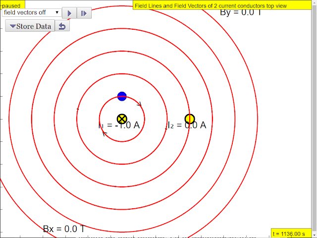 |
| current I1 = -1A #Magnetic #Field of 2 #current conducting wires #JavaScript #HTML5 Applet Simulation Model by Fu-Kwun Hwang and Loo Kang Wee |
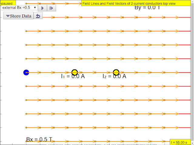 |
| external magnetic field Bx =0.5T #Magnetic #Field of 2 #current conducting wires #JavaScript #HTML5 Applet Simulation Model by Fu-Kwun Hwang and Loo Kang Wee |
 |
| external magnetic field Bx =0.5T,current I1 = -1A, I2 = 1A, showing the yellow resultant field lines that will result in force on wire1 to be down in the negative y direction, force on wire 2, force is positive y direction as the yellow field lines suggests closer separation at the top of wire 1 and bottom of wire 2. #Magnetic #Field of 2 #current conducting wires #JavaScript #HTML5 Applet Simulation Model by Fu-Kwun Hwang and Loo Kang Wee |
Scenario from Boon Chien.
example of simulation features
Research
[text]
Video
Electromagnetism (part 2): Working Principles of a DC Motor by ETDtogo https://www.youtube.com/watch?v=e1Uz3Dcav-g
Version:
- http://weelookang.blogspot.com/2016/06/magnetic-field-of-2-current-conducting.html
- http://www.phy.ntnu.edu.tw/ntnujava/index.php?topic=1290.0
- http://www.phy.ntnu.edu.tw/ntnujava/index.php?topic=1273
- ejs_users-sgeducation-lookang-MagneticField2Wire.jar remixed Jar by Loo Kang Wee and Fu-Kwun Hwang
- ejs_users-ntnu-fkh-twowiresBfield.jar original Jar by Fu-Kwun Hwang
Other Resources
-
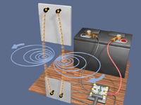
http://web.mit.edu/8.02t/www/802TEAL3D/teal_tour.htm Magnetostatics: found this fantastic graphics for An animation of the magnetic field and forces generated by two parallel wires is visualized when the current in the wires run in opposite directions. When the current is turned on, the resulting magnet field pressure between the wires pushes them apart.
http://web.mit.edu/8.02t/www/802TEAL3D/pirelli_images/Series_200.jpg
Frequently Asked Questions About Magnetic Fields from Current-Carrying Wires
- How does the magnetic field change as you transition from the field around a single straight wire to the field near a coil of wire? What contributes to the uniformity of the magnetic field inside a coil's center?
- As you move from considering the field around a single straight wire to the field near a coil (which can be thought of as multiple loops of wire), the magnetic field lines begin to concentrate and curve. The field lines around a single wire form concentric circles around the wire, but as the wires are arranged into a coil, the field lines from individual wires begin to interact. Inside a coil, particularly near its center, the field lines tend to become more uniform and parallel to the coil's axis. This is due to vector addition. The magnetic field at any point is the vector sum of the magnetic fields produced by each individual wire segment in the coil. Near the center, the magnetic fields from the different parts of the coil tend to align in the same direction, resulting in a stronger and more uniform field, as components of the field from different wires are directed in the same direction and add together. Components that would point in other directions tend to cancel out.
- In the simulation, there are arrows at each end of the wire, one red and one blue. Which color indicates the direction of the current, and how can you explain this?
- The red arrow typically indicates the direction of the conventional current in the wire. This convention is based on the idea that current flows from positive to negative. Therefore, when you observe the simulation, the red arrow will show the direction of the flow of positive charge carriers.
- What is magnetic flux, and how is it represented in the simulation's visualization? What do different colors mean in terms of flux intensity?
- Magnetic flux is a measure of the total magnetic field passing through a given area. In simpler terms, it represents how much magnetic field is "poking through" a surface. The simulation visualizes magnetic flux using color mapping. Different colors represent different levels of flux intensity. Usually, darker or more intense colors (like pink) represent regions of higher magnetic flux, meaning there is a higher concentration of magnetic field lines passing through that region. Conversely, lighter colors (like yellow) typically represent regions with lower flux. Higher flux implies both a stronger magnetic field and that the field is passing through the surface more perpendicularly, thus, the flux is maximized. The more field lines that are concentrated in an area, the higher the flux, and the more perpendicular those lines are to a given surface, the higher the flux.
- What are some practical applications of understanding the magnetic fields generated by current-carrying wires?
- Understanding the magnetic fields created by current-carrying wires is fundamental to many technological applications. Some key applications include: the working principles of electric motors (as shown in the video link provided), which convert electrical energy into mechanical motion; transformers, which use electromagnetic induction to change voltage levels; and electromagnets, which can be turned on and off by controlling the flow of current. Furthermore, this principle is at the heart of magnetic storage devices like hard drives, where tiny magnets are used to store data by controlling electrical currents.
- What tools or platforms are used to create the simulation mentioned in the text?
- The simulation described in the text was created using the Easy Java Simulations (EJS) modeling tool, which is described as an open-source modeling and authoring tool. Additionally, the simulation has been adapted using JavaScript and HTML5 to make it accessible on various devices.
- Where can I find similar simulations or learn more about physics simulations?
- The provided text includes links to several resources, including the Open Source Physics ComPADRE collection (http://www.compadre.org/OSP/) and the EJS website (http://www.um.es/fem/Ejs/). These sites offer numerous physics simulations and information about creating your own. Additionally, there are links to MIT’s TEAL project which provides excellent visualizations and to youtube videos and other resources embedded in the main resource.
- How does the direction of the current in the wires affect the magnetic field, and what does the example scenario involving Bx=0.5T, I1=-1A, and I2=1A, show us about forces between wires? The direction of current flow in wires has a significant impact on the magnetic field's direction and, consequently, the forces between the wires. If currents in two parallel wires flow in the same direction, they create magnetic fields that attract each other and if the currents flow in the opposite direction, they repel each other. In the given scenario of external magnetic field Bx=0.5T, and I1=-1A and I2=1A, the simulation would demonstrate that wire 1 with a negative current direction has a force pushing it downward (negative y-direction) and wire 2 with a positive current direction has a force pushing it upward (positive y direction). The yellow resultant field lines show closer separation at the top of wire 1 and bottom of wire 2, indicating that force will tend to move the wires toward areas with lower separation of magnetic field lines.
- What are the license and usage terms for the simulations and related materials?
- The content is licensed under a Creative Commons Attribution-Share Alike 4.0 Singapore License. This generally means you are free to share and adapt the material for non-commercial purposes, provided that you give appropriate credit and share any adaptations under the same license. However, commercial use of the EasyJavaScriptSimulations Library requires contacting This email address is being protected from spambots. You need JavaScript enabled to view it. directly and may involve additional agreements.
- Details
- Written by Loo Kang Wee
- Parent Category: 05 Electricity and Magnetism
- Category: 08 Electromagnetism
- Hits: 18131


