
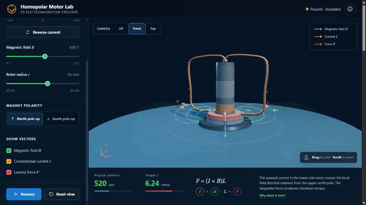
Homopolar Motor 3D Lab makes the invisible physics of the simplest electric motor visible. Students can orbit a battery–magnet–wire model, trace the closed current path, inspect smooth magnetic-field loops and compare the local current, field and force vectors that produce rotation.
The activity is designed to connect the global picture of a magnet's field—from its north pole through space and back into its south pole—with the local radial field component that acts on the current-carrying conductor.
Resource type: Standalone HTML5 3D simulation, downloadable ZIP package and guided electromagnetism inquiry
Topic: Homopolar motor, motor effect, magnetic force, current, magnetic field, torque and vector direction
Run the 3D simulation Download ZIP package Read the blog post Find it in the digital library
Why the simplest motor is a rich physics problem
A battery, a cylindrical magnet and a bent copper wire can make a motor with no commutator and no wound coil. Once the wire touches the battery terminal and the magnet, the circuit closes. Current passes through a region where the magnet's field has a strong radial component. The magnetic force is then tangential, giving the wire a turning effect about the vertical axis.
The device is simple to build but difficult to interpret from a flat diagram. The current path bends through several surfaces, the magnetic field changes direction in space, and the resulting force is perpendicular to both. The interactive lets students rotate the apparatus and separate the three vector overlays before bringing them together.
The magnetic field: global loops and a local vector
Magnetic field lines do not start or stop in empty space. Outside the cylindrical magnet, the lines leave the north pole, curve smoothly around the magnet and enter the south pole. Inside the magnet, the loop continues back towards the north pole. The model therefore depicts rounded closed field lines rather than a set of disconnected radial arrows.
Near the edge of the magnet, however, the field has a strong radial component. That local component is the one used when finding the force on the current-carrying conductor. The model deliberately shows both representations: complete field lines for the global field structure and a B vector at the interaction point for the local direction.
Current, field and force
For a straight conductor in a magnetic field, the full vector relationship is F = I(L × B). In the perpendicular case, the magnitude simplifies to F = IBL. The direction can be read from the vector relationship between the current direction and the magnetic field, represented in the lab as I × B, while the scalar length L sets the magnitude.
The force is tangential to the path around the axis. Because it acts at a distance r from the axis, it produces a torque. In the idealised right-angle model, τ ≈ IBLr. Increasing I, B, L or r increases the available turning effect.
What students can change
- Current: vary its magnitude or reverse its direction.
- Magnetic field: change its strength or reverse the magnet polarity.
- Rotor radius: change the moment arm and observe the predicted torque.
- Vector overlays: show or hide I, B and F independently.
- Motion: pause, run, reset and orbit the 3D view.
Suggested inquiry sequence
- Trace the complete circuit and explain why an open contact prevents rotation.
- Show only the magnetic field. Identify where the lines leave the north pole and return to the south pole.
- Show I, B and F near the contact region and describe their three-dimensional relationship.
- Reverse only the current and predict the new rotation direction.
- Reverse only the magnet polarity, then reverse both current and polarity.
- Increase current or field strength and explain the change using F = IBL and τ ≈ IBLr.
Five questions for learners
- Why must the copper wire touch both the battery terminal and the magnet?
- How are I, B and F oriented near the wire–magnet contact?
- Why does reversing either current or magnet polarity reverse the rotation?
- Why does reversing both current and polarity restore the original rotation direction?
- Which controls change force magnitude without changing force direction?
Common misconception to discuss
The magnetic field is not “radially outward everywhere.” Its lines form closed loops. Close to the magnet's rim, a radial component can dominate and is especially relevant to the motor effect. Distinguishing a complete field line from a vector at one point helps students reconcile these two descriptions.
Credits and open learning
This original simulation and learning resource were made by lookang for Open Educational Resources / Open Source Physics @ Singapore. The physical arrangement was informed by the JavaLab homopolar motor explanation; no source code or page layout was copied.
Download the complete ZIP package for offline use, classroom sharing or adaptation.
Explore more resources at iwant2study.org and in the OSPSG Electromagnetism collection.